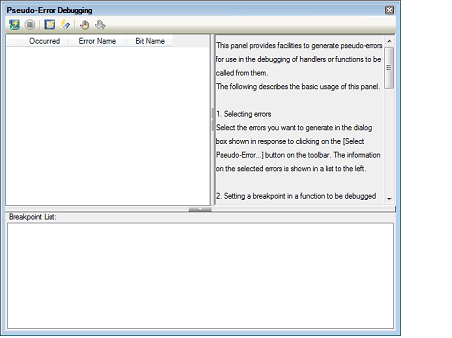
Pseudo-error debugging is a feature for generating pseudo-errors which are difficult to reproduce on the real machine. You can use this feature to check the operation of the reset routine or handlers called in response to errors, or functions to be called from within handlers, and then debug the code.
The Error Control Module (ECM)Note is used to generate such pseudo-errors.
See the chapter of the ECM in User's Manual: Hardware of each device for details. A device without the ECM does not have a chapter of the ECM in its manual. In such a case, pseudo-error debugging cannot be used. |
Open the Solution List panel and click the [GO] button for Pseudo-Error Debugging to display the Pseudo-Error Debugging panel [Full-spec emulator][E1][E20].

For a device that does not support pseudo-error debugging, pseudo-error debugging is not displayed on the Solution List panel. Even for a device that supports pseudo-error debugging, the [GO] button is nullified when the simulator is being used or the debug tool has not been connected. |
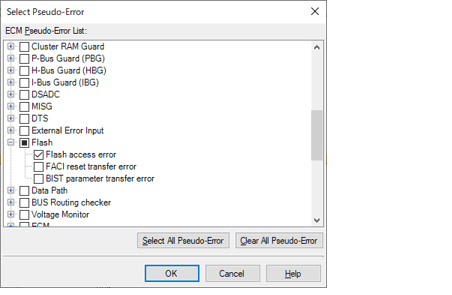
On the Pseudo-Error Debugging panel [Full-spec emulator][E1][E20], click  . The Select Pseudo-Error dialog box [Full-spec emulator][E1][E20] will open.

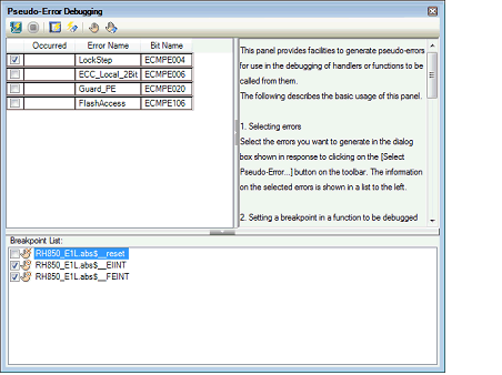
A list of errors supported by the pseudo-error debugging feature is displayed in the Select Pseudo-Error dialog box [Full-spec emulator][E1][E20]. Select the check box of the error you wish to generate and click the [OK] button. The selected error is displayed in the Pseudo-Error Debugging panel [Full-spec emulator][E1][E20].

See User's Manual: Hardware for details on errors. [Bit Name] shows the names of individual bits in ECM pseudo error trigger registers (e.g. ECMPE0) listed in the chapter of the ECM. |
Click  on the Pseudo-Error Debugging panel [Full-spec emulator][E1][E20] to open the Breakpoint Setting dialog box [Full-spec emulator][E1][E20]. Entering the address expression of a handler or reset routine to be called in response to an error enables a break to occur at that address after the error is generated. A symbol, such as a handler name, can also be entered.

Enter an address in the ROM area. A breakpoint cannot be set if an address in the RAM area is specified. |
Clicking |
Click  on the Pseudo-Error Debugging panel [Full-spec emulator][E1][E20]. An error is generated using an ECM pseudo-error trigger register (e.g. ECMPE0). An interrupt or reset is generated based on the user setting. A break occurs when execution passes the address specified in the Breakpoint Setting dialog box [Full-spec emulator][E1][E20].
Pseudo-error debugging is not supported in Async debug mode. When Async debug mode has been selected, click |
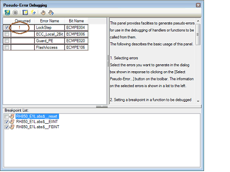
When a break occurs, the ECM master/checker error source status register (e.g. ECMmESSTR0) is referenced and "!" is displayed for the generated error.

If the setting of the ECM master/checker error source status register (e.g. ECMmESSTR0) has been cleared, [!] is not displayed even when an ECM error occurs. |
For RH850/G4MH devices, the number of occurrences of a pseudo-error that can be counted is up to three. If the corresponding pseudo-error occurs more times than this, "!" will be displayed as the counted number of times the pseudo-error occurred. |
To cause an RH850/P1x-series MCU to be internally reset by a pseudo-error, set up an ECM pseudo-error trigger register from the user program. A special instruction sequence is required for writing to this register since it is protected. For details, refer to the section of write-protected registers in User’s Manual: Hardware for the MCU in use. |
Do not set a breakpoint at the current PC address in pseudo-error debugging. When it is set, interrupts and internal reset will not occur. |
If you wish to set another breakpoint via a source editor or the Disassemble panel at the address where a breakpoint has been set for pseudo-error debugging, designate it as a hardware breakpoint. Setting a software breakpoint in this case will lead to an error when pseudo-error debugging is started. |
The following pseudo-error debugging wasn't being supported in RH850/D1L group and RH850/D1M group. |
 will not cause a break to occur at a breakpoint that was not set in this dialog box. The program can be forcibly stopped.
 after switching the value of the [Debug mode] property in the [Multi-core] category on the