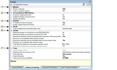
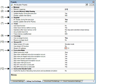
The [Debug Tool Settings] tab displays detailed information for each category shown below and changes settings made on it.
(2) [Access Memory While Running]
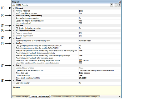
(4) [E2 Expansion Interface] [E2]
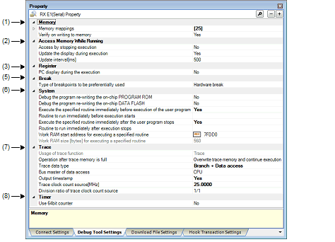
(5) [Break] [E1] [E20] [EZ Emulator]
(6) [System] [E1] [E20] [EZ Emulator]
(8) [Timer] [E1] [E20] [EZ Emulator]
(11) [Execution Mode] [Simulator]
(12) [Instruction Decode Cache] [Simulator]
(13) [Coverage] [E20 [RX71M, RX65x, and RX64M Groups]]
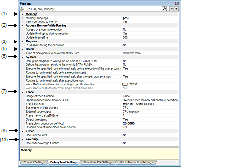
[Description of each category]
This category displays detailed information on memory and changes memory settings.
For details about the displayed types of memory, see the section where the Memory Mapping dialog box is described.
|
Displays the current state of memory mapping per typeNote 1 of memory area. |
|||
|
[Sum total by microcontroller's inherent type of memory mapped area] |
|||
|
Specification by Memory Mapping dialog box
The Memory Mapping dialog box is opened by clicking the [...] button that is displayed at the right edge in the column when this property is selected. |
|||
|
Displays the state of memory mapping per type of memory area. Note that when the "+" mark for each memory type is clicked, the next detailed information is displayed. |
|||
|
Specify whether or not to perform a verify check when memory values are initialized. |
|||
The access width and the endian can only be changed when [Memory type] is an external area and the debug tool is disconnected. Also, the specifiable value differs with each selected microcontroller. |
The endian information differs in displayed contents and specifiable values depending on [Memory Type]. |
Specify one of the following by selecting from the drop-down list:
Same as MCU endian or different from MCU endian
One of the following is displayed:
Little-endian data or big-endian data
Specify one of the following:
Little-endian data or big-endian data
No endian information is displayed.
This category displays detailed information on memory access during program execution and the realtime display update function (see “2.11.1.4 Displaying and changing memory contents during program execution”) and changes memory access settings.
|
For a memory area not accessible during program execution, specify whether access to the area is permitted. |
|||
|
Execution is temporarily halted before a read or write is performed. |
|||
|
Specify whether or not to update the displayed content of the Watch panel/Memory panel during program execution. |
|||
|
Specify the interval in 100 ms unit to update the displayed contents of the Watch panel or Memory panel while executing a program. Note that this property is displayed only when you selected [Yes] in the [Update display during the execution] property. |
|||
|
An integer in the range 100 to 65500 (Unit: fractions below 100 ms rounded up) |
|||
|
Specify whether RRM area is automatically set. Note that this property is displayed only when [Real-time RAM Monitor] is specified in the [Usage of trace function] property and also [Yes] is specified in the [Update display during the execution] property. |
|||
Change PC value display in the Status bar and display updating intervals during program execution.
|
Specify whether the PC value is displayed Note during program execution. |
||||
|
PC value is displayed in the Status bar during execution. |
||||
|
PC value is not displayed in the status bar during execution. "Running" is displayed in the Status bar. |
||||
|
Specify an update interval in 100 ms units for the PC value which is displayed in the Status bar during program execution. Note that this property is displayed only when you've selected [Yes] in the [PC display during the execution] property. |
||||
|
An integer in the range 100 to 65500 (Unit: fractions below 100 ms rounded up) |
||||
[E1/E20/EZ Emulator [RX100 Series]] |
The detailed information on the E2 expansion interface is displayed and its configuration can be changed.
This category displays detailed information on the break function and changes break settings.
|
Specify the type of breakpoint that will be used first before the other when you set a breakpoint at the source line or execution address by clicking once with the mouse on the Editor panel/Disassemble panel. |
||||
Displays detailed information on emulation system or changes settings made in it.
|
Specify whether or not to debug a program that involves rewriting the on-chip program ROM (e.g., a program making use of ROM P/E mode).Note 1, Note 2 |
|||
|
By selecting from the drop-down list However, changeable only when disconnected from the debug tool |
|||
|
A program that involves rewriting the on-chip program ROM is debugged. |
|||
|
A program that involves rewriting the on-chip program ROM is not debugged. |
|||
|
Specify whether or not to debug a program that involves rewriting the on-chip data flash (e.g., a program making use of data flash P/E mode).Note 1, Note 2, Note 4 |
|||
|
By selecting from the drop-down list However, changeable only when disconnected from the debug tool |
|||
|
A program that involves rewriting the on-chip data flash is debugged. |
|||
|
A program that involves rewriting the on-chip data flash is not debugged. |
|||
|
Execute the specified routine immediately before execution of the user program |
Specify whether or not to run a specified routine immediately before program execution. |
||
|
A specified routine is run immediately before program execution. |
|||
|
A specified routine is not run immediately before program execution. |
|||
|
Specify the address to be executed immediately before program execution. This property is displayed only when [Yes] is specified in the [Execute the specified routine immediately before execution of the user program] property. |
|||
|
Execute the specified routine immediately after the user program stops |
Specify whether or not to run a specified routine immediately after the program breaks. |
||
|
A specified routine is not run immediately after program breaks. |
|||
|
Specify the address to be executed immediately after the program breaks. This property is displayed only when [Yes] is specified in the [Execute the specified routine immediately after the user program stops] property. |
|||
|
Specify the address where the work RAM for use in execution of the specified routine starts. Specify an address value that is a multiple of four bytes. If the entered value is not a multiple of four bytes, the value is automatically corrected. This property is displayed only when you have selected [Yes] either for the [Execute the specified routine immediately before execution of the user program] or [Execute the specified routine immediately after the user program stops] property. |
|||
|
Indicates the size of the work RAM for use in execution of the specified routine. This property is displayed only when you have selected [Yes] either for the [Execute the specified routine immediately before execution of the user program] or [Execute the specified routine immediately after the user program stops] property. |
|||
[E1] [E20] [EZ Emulator] |
[E1] [E20] [EZ Emulator] |
[RX71M and RX64M Groups] |
This category displays detailed information on the trace function and changes trace settings.
[E20(JTAG) [RX600 Series]] |
|
Specify whether the trace function is used as real-time RAM monitor function (RRM function). |
||||
|
By selecting from the drop-down list |
||||
|
Real-time RAM monitor function (RRM function) is used preferentially. |
||||
|
Specify whether or not to clear the trace memory before execution. |
||||
|
Specify the operation after the trace memory is full with the collected trace data. |
||||
|
Continues overwriting trace data even after trace memory is used up. |
||||
|
Stops running the program and overwriting trace data when trace memory is used up. |
||||
|
One of the following as selected from the drop-down list: Branch, Branch + Data access, Data access, Branch + Data access (without Access data), or Data access (without Access data) |
||||
|
Specify the start address for the trace area without access data. |
||||
|
Specify the end address for the trace area without access data. |
||||
|
Specify the bus master which generated the data access. This property can be selected only when [Branch+Data access] or [Data access] is specified in the [Trace data type] property. When [Real-time RAM Monitor] is selected in the [Usage of trace function] property, this property is fixed to [CPU]. |
||||
|
The results of data access from CPU are displayed on the trace panel. |
||||
|
The results of data access from DMAC/DTC are displayed on the trace panel. |
||||
|
Specify whether timestamp information is added to the collected trace dataNote 3. This property is selectable only when you've specified [Trace] in the [Usage of trace function] property. |
||||
|
Enter a count source with which a timestamp is calculated from a count value. However, this item is displayed only when you've selected [Yes] in the [Output timestamp] property. |
||||
|
Specify the division ratio of trace clock count source for the timestamp. This property is displayed only when [Yes] is selected in the [Output timestamp] property. The frequency specified in the [Trace clock count source[MHz]] property is divided by the specified value (the frequency is multiplied by 1/n) and one cycle of the obtained frequency is used as the unit for timestamp count (the frequency for count value 1). |
||||
|
The frequency of the timestamp count source is used without change. |
||||
|
The frequency of the timestamp count source is multiplied by 1/16 before use. |
||||
|
The frequency of the timestamp count source is multiplied by 1/256 before use. |
||||
|
The frequency of the timestamp count source is multiplied by 1/4096 before use. |
||||
|
Specify a display method by which the trace time on the Trace panel is displayed. |
||||
|
Specify the size of memory that holds trace data by a number of trace frames Note 2. |
||||
If [Start Tracing] or [Stop Tracing] on the context menu is selected on the Editor panel/Disassemble panel, this property is automatically changed to [Yes]. |
The trade frame represents one unit of trace data. |
This property is fixed to [No] when an RX100-series microcontroller is in use. Timestamp information is not included in trace data. |
This category displays detailed information on the timer function and changes timer settings.
|
Specify whether or not to use a 64-bit measurement counter. However, if [Yes] is specified, measurement is performed in only one section. |
||||
|
Specify whether the coverage measurement result is loaded or saved when connected to or disconnected from the debug tool. This property is displayed only when you selected [Yes] in the [Use coverage function] property. |
||||
|
By selecting from the drop-down list Changeable only when disconnected from the debug tool, however. |
||||
|
A simulator-inherent I/O method is used. Standard I/O and file I/O can be used. |
||||
|
Specify whether or not to use the stream I/O function. This property is displayed only when [Simulator mode] is specified in the [Select stream I/O mode] property. |
||||
|
Specify the start position of a stream I/O that is used to perform standard I/O or file I/O from the user program. This property is displayed only when [Simulator mode] is specified in the [Select stream I/O mode] property. |
||||
|
Specify whether or not to stop execution of the user program when a simulation error or an exception occurs. |
||||
|
Specify whether or not to stop execution of the user program when an undefined instruction exception occurs. This property is displayed only when [Stop] is specified in the [Select execution mode] property. |
||||
|
Specify whether or not to stop execution of the user program when a privileged instruction exception occurs. This property is displayed only when [Stop] is specified in the [Select execution mode] property. |
||||
|
Specify whether or not to stop execution of the user program when an access exception occurs. This property is displayed only when there is MPU module in the [Peripheral function simulation module] property and also [Stop] is specified in the [Select execution mode] property. |
||||
|
Specify whether or not to stop execution of the user program when a floating-point exception occurs. This property is displayed only when [Stop] is specified in the [Select execution mode] property. |
||||
|
Specify whether or not to stop execution of the user program when an interrupt occurs. This property is displayed only when [Stop] is specified in the [Select execution mode] property. |
||||
|
Specify whether or not to stop execution of the user program when an NT instruction is executed. This property is displayed only when [Stop] is specified in the [Select execution mode] property. |
||||
|
Specify whether or not to stop execution of the user program when a BRK instruction is executed. This property is displayed only when [Stop] is specified in the [Select execution mode] property. |
||||
|
Cache the results of decoding instructions and accelerate simulation |
Specify whether or not to use the instruction decode cache function. |
|||
|
By selecting from the drop-down list However, changeable only when CS+ is disconnected from the debug tool |
||||
|
Specify the coverage measurement priority of the coverage data. This property is displayed only when [Yes] is specified in the [Use code coverage function] property. |
||||
|
Coverage measurement takes priority. CPU execution may stop to output coverage data, affecting real-time performance of program execution. |
||||
|
Specify the ranges where you want to measure coverage. The number of coverage area of measurement that can be registered is displayed as a main property. [Start address] and [Size of the coverage area of measurement [Mbytes]] are expanded to display in the sub-property. Specify a multiple of 4 Mbytes as the start address (if the specified value is not a multiple of 4M bytes, the value is automatically corrected). This property is displayed only when you selected [Yes] in the [Use coverage function] property. |
||||
|
By entering directly from the keyboard |
||||
|
Specify whether the coverage measurement result is loaded or saved when connected to or disconnected from the debug tool. This property is displayed only when you selected [Yes] in the [Use coverage function] property. |
||||