The [Connect Settings] tab displays detailed information for each category shown below and changes settings made on it.
(4) [Connection with Emulator] [E1] [E20]
(5) [Connection with Target Board] [E1] [E20] [EZ Emulator]
(6) [E2 Expansion Interface] [E2]
(7) [Flash] [E1] [E20] [EZ Emulator]
(8) [Operating Modes of CPU] [E1] [E20] [EZ Emulator]
(9) [External Flash] [E1] [E20]
(10) [Peripheral Function Simulation] [Simulator]

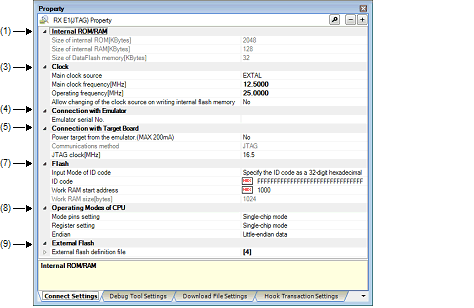
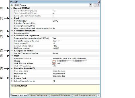
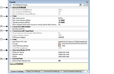
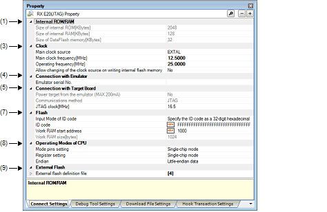
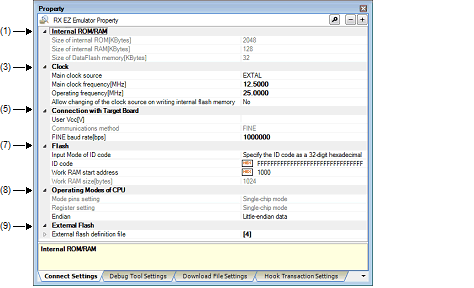
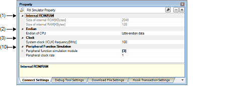
[Description of each category]
Displays detailed information on internal ROM/RAM.
Displays detailed information on CPU endian and modifies its settings.
This category displays detailed information on clock and changes clock settings.
|
Specify the main clock from the EXTAL frequency and internal HOCO. |
|||
|
By selecting from the drop-down list However, changeable only when disconnected from the debug tool |
|||
|
Specify EXTAL frequency in MHz units. Note that this property is enabled only when [EXTAL] is specified in the [Main clock source [E1] [E20] [EZ Emulator]] property. |
|||
|
By entering directly from the keyboard However, changeable only when disconnected from the debug tool |
|||
|
Allow to change the clock source on writing internal flash memory |
Specify whether or not to allow manipulation of the main clock source by debugger when internal flash memory is rewritten. |
||
|
By selecting from the drop-down list However, changeable only when disconnected from the debug tool |
|||
|
By entering directly from the keyboard However, changeable only when disconnected from the debug tool |
|||
When E1(JTAG) or E1(Serial) is selected in the debug tool used, serial Nos. of E1 emulator are enumerated. Similarly, when E20(Serial) or E20(JTAG) is selected, serial Nos. of E20 emulator are enumerated. |
This category displays detailed information on a state of connection with the target board and changes connection settings.
|
Specify the value of the microcontroller’s operating voltage that is actually supplied to the user board. |
||||
|
By entering directly from the keyboard However, changeable only when disconnected from the debug tool. |
||||
|
Specify whether power is supplied from E1 to the target system. The E20 does not support the power supply function. Therefore, the displayed property value is [No]. |
||||
|
By selecting from the drop-down list |
||||
|
Select the interface for supplying the power to the target board from the emulator. |
||||
|
Specify the voltage supplied from E1 to the target board. Note that this property is displayed only when you selected [Yes] in the [Power target from the emulator (MAX 200mA) [E1] [E20]] property. |
||||
|
By selecting from the drop-down list. However, changeable only when disconnected from the debug tool. Select from the drop-down list or directly enter from the keyboard. |
||||
|
One of the following as selected from the drop-down list: Note
Directly enter the numbers ranged below |
||||
|
Displays the communication method to be connected when communication between the emulator and the CPU on target system is performed. |
||||
|
Not changeable or by selecting from the drop-down list Whether this property can be changed differs with the type of the selected microcontroller and the communication method. See "2.2.1 Confirm the connection to a host machine" for the relationship between types of the microcontroller and the communication method. |
||||
|
Specify JTAG communication speed between the emulator and the CPU on target system. Note that this property is displayed only when [JTAG] is specified in the [Communication method] property. |
||||
|
By selecting from the drop-down list However, changeable only when disconnected from the debug tool |
||||
|
Specify FINE communication speed between the emulator and the CPU on target system. Note that this property is displayed only when [FINE] is specified in the [Communication method] property. |
||||
|
By selecting from the drop-down list However, changeable only when disconnected from the debug tool |
||||
The detailed information on the E2 expansion interface is displayed and its configuration can be changed.
|
Uses the E2 expansion interface by the power supplied from the target. |
||||
|
Uses the E2 expansion interface by the supplied power from the emulator. |
||||
This category displays detailed information on flash memory rewriting and changes rewrite settings.
The work RAM area can also be used by the user program because the emulator saves and restores data in this area. Note, however, that the work RAM area is not specifiable as: |
Displays detailed information on the microcontroller's operation modes or changes settings made in it.
|
By selecting from the drop-down list However, changeable only when disconnected from the debug tool |
||||
|
Specify whether to erase the USB boot program in the user boot area when you are starting up the emulator in the user boot mode by using a microcontroller in which the USB boot program is stored. This property is displayed only when [User boot mode] is selected for the [Mode pins setting] property. Note that this is not displayed for an microcontroller in which the USB boot program in the user boot area does not need to be erased when you are starting up the emulator. |
||||
|
By selecting from the drop-down list However, changeable only when disconnected from the debug tool |
||||
|
Does not allow erasing the USB boot program in the user boot area |
||||
|
By selecting from the drop-down list However, changeable only when disconnected from the debug tool |
||||
|
Single-chip mode, on-chip ROM enabled extended mode or on-chip ROM disabled extended mode |
||||
|
By selecting from the drop-down list |
||||
|
Specify whether to change the start bank before connecting to the debug tool. |
||||
|
Specify the start bank to be changed before connecting to the debug tool. |
||||
If a microcontroller with an MDE pin is selected, be sure that the project's endian and the microcontroller's MDE pin state match. If endians are different, the project and microcontroller cannot be connected correctly. |
Displays detailed information on external flash or changes settings made in it.
Any settings made in this section are not reflected when the microcontroller is operating in single-chip mode. |
Displays detailed information on peripheral function simulation or changes settings made in it.