CHAPTER 9 INTERRUPT MANAGEMENT FUNCTIONS
The RI78V4 provides as interrupt management functions related to the interrupt handlers activated when a maskable interrupt is occurred.
In the RI78V4, interrupt servicing managed by the RI78V4 is called "interrupt handler", which is distinguished from interrupt servicing that operates without being managed by the RI78V4.
* It is also possible to assign a level of 2 or 3 to an application that disables multiple interrupts.
Note 1 The interrupt priority level is set using the priority specification flag register of the target CPU.
Note 2 The RI78V4 does not execute initialization of hardware that creates interrupts (clock controller, etc.). This initialization processing must therefore be coded by the user in the Boot Processing or Initialization Routine.
Interrupt entry processing is a routine dedicated to entry processing that is extracted as a user-own coding module to assign instructions to branch to relevant processing (such as Interrupt Handlers or Boot Processing), to the vector table address to which the CPU forcibly passes the control when an interrupt occurs.
When the interrupt handler is described by C language (the TA_HLNG attribute is specified in a interrupt handler definition of the system configuration file(DEF_INH)), the user does not have to describe interrupt entry processing because of the C compiler outputing "interrupt entry processing which corresponds to an interrupt request name" automatically.
When the interrupt handler is described by Assembly language (the TA_ASM attribute is specified in a interrupt handler definition of the system configuration file(DEF_INH)), the user has to describe interrupt entry processing. Futher it is necessory to describe by an assembly language about branch to boot processing.
The code of interrupt entry processing varies depending on whether the relevant processing (Interrupt Handlers, Boot Processing, or the like) is allocated to the near area or to the far area.
[ When the relevant processing (Interrupt Handlers, Boot Processing, or the like) is allocated to the near area ]
.PUBLIC _func_inthdr _func_inthdr .VECTOR 0x002C ;Jump to boot processing .SECTION .text, TEXT ;Vector table address setting _func_inthdr: ............ ;Main processing |
[ When the relevant processing (Interrupt Handlers, Boot Processing, or the like) is allocated to the far area ]
Interrupt entry processing is a routine dedicated to processing of entries called without using the RI78V4 when an interrupt occurs. Therefore, note the following points when coding interrupt entry processing.
- Coding method
Code interrupt entry processing in assembly language, in formats compliant with the assembler's function calling rules.
Code interrupt entry processing in assembly language, in formats compliant with the assembler's function calling rules.
- Stack switching
No stack requiring switching exists in interrupt entry processing execution. The code regarding stack switching during interrupt entry processing is therefore not required.
No stack requiring switching exists in interrupt entry processing execution. The code regarding stack switching during interrupt entry processing is therefore not required.
- Service call issuance
The RI78V4 prohibits issuance of service calls in interrupt entry processing.
The RI78V4 prohibits issuance of service calls in interrupt entry processing.
The interrupt handler is a routine dedicated to interrupt servicing that is activated when an interrupt occurs, and is called from Interrupt Entry Processing.
The RI78V4 handles the interrupt handler as a "non-task (module independent from tasks)". Therefore, even if a task with the highest priority in the system is being executed, the processing is suspended when an interrupt occurs, and the control is passed to the interrupt handler.
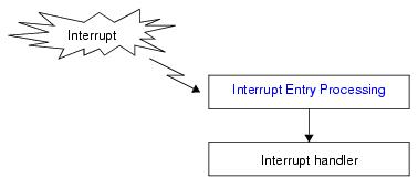
The following shows a processing flow from when an interrupt occurs until the control is passed to the interrupt handler.
Interrupt handler registration is realized by coding Interrupt Entry Processing (branch instruction to interrupt handler) to the vector table address to which the CPU forcibly passes control upon occurrence of an interrupt.
The code of Interrupt Entry Processing varies depending on whether the interrupt handler is allocated to the near area or to the far area.
When the interrupt handler is described by C language (the TA_HLNG attribute is specified in a interrupt handler definition of the system configuration file(DEF_INH)), the user does not have to describe interrupt entry processing because of the C compiler outputing "interrupt entry processing which corresponds to an interrupt request name" automatically.
When the interrupt handler is described by Assembly language (the TA_ASM attribute is specified in a interrupt handler definition of the system configuration file(DEF_INH)), the user has to describe interrupt entry processing.
When coding interrupt handlers in C, use void type functions that do not have arguments (any function name is fine) .
The code of interrupt depending on whether the interrupt handler is allocated to the near area or to the far area.
Note 1 The TA_HLNG attribute and the TA_NEAR attribute are specified in a definition of a interrupt handler in the system configuration file (DEF_INH).
Note 2 The the #pragma rtos_interrupt directive is defined in the file "kernel_id.h" (CF78V4 outputs automatically). Therefore please the file "kernel_id.h" be sure to do include.
Note 1 The TA_HLNG attribute and the TA_FAR attribute are specified in a definition of a interrupt handler in the system configuration file (DEF_INH).
Note 2 The the #pragma rtos_interrupt directive is defined in the file "kernel_id.h" (CF78V4 outputs automatically). Therefore please the file "kernel_id.h" be sure to do include.
When coding interrupt handlers in assembly language, use void type functions that do not have arguments (function: any).
The code of interrupt depending on whether the interrupt handler is allocated to the near area or to the far area.
- When the interrupt handler is allocated to the near area
Saves AX register and stores the vector table address when an interrupt occurs, calls processing to switch to the system stack (function name: _kernel_int_entry), and then call end processing at the end of the interrupt handler (function name: _kernel_int_exit). A near attribute section is specified as an allocated section of the interrupt handler.
Saves AX register and stores the vector table address when an interrupt occurs, calls processing to switch to the system stack (function name: _kernel_int_entry), and then call end processing at the end of the interrupt handler (function name: _kernel_int_exit). A near attribute section is specified as an allocated section of the interrupt handler.
Note The TA_ASM attribute and the TA_NEAR attribute are specified in a definition of a interrupt handler in the system configuration file (DEF_INH).
- When the interrupt handler is allocated to the far area
Calls processing to switch to the system stack (function name: _kernel_int_entry), and then call end processing at the end of the interrupt handler (function name: _kernel_int_exit). A far attribute section is specified as an allocated section of the interrupt handler.
Calls processing to switch to the system stack (function name: _kernel_int_entry), and then call end processing at the end of the interrupt handler (function name: _kernel_int_exit). A far attribute section is specified as an allocated section of the interrupt handler.
Note 1 The TA_ASM attribute and the TA_FAR attribute are specified in a definition of a interrupt handler in the system configuration file (DEF_INH).
Note 2 When allocating a interrupt handler in far area, the far branch information is needed. In other words, it jumps from the vector table address to far branch information and jumps to a interrupt handler from there. CF78V4 outputs this far branch information automatically in a system information table file.
Note 3 CF78V4 outputs processing code that saves AX register and sets the vector table address of the factor automatically in a system information table file.
Moreover, the RI78V4 executes "original pre-processing" when passing control to the interrupt handler, as well as "original post-processing" when regaining control from the interrupt handler.
- Coding method
Code interrupt handlers using C or assembly language in the format shown in "9.3.2 Basic form of interrupt handlers".
Code interrupt handlers using C or assembly language in the format shown in "9.3.2 Basic form of interrupt handlers".
- Stack switching
When the interrupt handler is described by C language, the user does not have to describe to switch to the system stack (calls _kernel_int_entry) because of the C compiler outputing this code automatically. When the interrupt handler is described by assembly language, saves AX register and stores the vector table address when an interrupt occurs, calls processing to switch to the system stack (function name: _kernel_int_entry), and then call end processing at the end of the interrupt handler (function name: _kernel_int_exit).
When the interrupt handler is described by C language, the user does not have to describe to switch to the system stack (calls _kernel_int_entry) because of the C compiler outputing this code automatically. When the interrupt handler is described by assembly language, saves AX register and stores the vector table address when an interrupt occurs, calls processing to switch to the system stack (function name: _kernel_int_entry), and then call end processing at the end of the interrupt handler (function name: _kernel_int_exit).
- Saving/storing of data in register
When the interrupt handler is described by C language, the user does not have to describe to switch to the system stack (calls _kernel_int_entry) because of the C compiler outputing this code automatically. When the interrupt handler is described by assembly language, data of general-purpose registers (AX, BC, DE, HL) and registers ES CS is saved and restored in that function execution, by explicitly calling register data save processing (function name: _kernel_int_entry) at the beginning of the interrupt handler, and calling data restore processing (function name: _kernel_int_exit) at the end of the interrupt handler.
When the interrupt handler is described by C language, the user does not have to describe to switch to the system stack (calls _kernel_int_entry) because of the C compiler outputing this code automatically. When the interrupt handler is described by assembly language, data of general-purpose registers (AX, BC, DE, HL) and registers ES CS is saved and restored in that function execution, by explicitly calling register data save processing (function name: _kernel_int_entry) at the beginning of the interrupt handler, and calling data restore processing (function name: _kernel_int_exit) at the end of the interrupt handler.
- Interrupt status
The RI78V4 goes into the following state when passing control to an interrupt handler.
Consequently, after control has passed to an interrupt handler, if an interrupt occurs with a higher precedence than the current level, then multiple interrupts can be processed.
The RI78V4 goes into the following state when passing control to an interrupt handler.
Consequently, after control has passed to an interrupt handler, if an interrupt occurs with a higher precedence than the current level, then multiple interrupts can be processed.
Note Even if the acceptance of maskable interrupts is disabled inside an interrupt handler (IE = 0), it will be enabled (IE = 1) after control returns from the interrupt handler.
- Service call issuance
The RI78V4 handles the interrupt handler as a "non-task".
Service calls that can be issued in interrupt handlers are limited to the service calls that can be issued from non-tasks.
The RI78V4 handles the interrupt handler as a "non-task".
Service calls that can be issued in interrupt handlers are limited to the service calls that can be issued from non-tasks.
Note 1 For details on the valid issuance range of each service call, refer to Table 12-8 to Table 12-17.
Note 2 If a service call (ichg_pri, isig_sem, etc.) accompanying dispatch processing (task scheduling processing) is issued in order to quickly complete the processing in the interrupt handler during the interval until the processing in the interrupt handler ends, the RI78V4 executes only processing such as queue manipulation, counter manipulation, etc., and the actual dispatch processing is delayed until a return instruction is issued by the interrupt handler, upon which the actual dispatch processing is performed in batch.
The microcontroller manages four levels of interrupts: level 0 to level 3. On the RI78V4, the interrupt levels at which service calls can be issued from an interrupt are permanently set to levels 2 and 3, these are treated as the interrupt levels managed by the RI78V4.
- Interrupt levels 2 and 3 are managed by the RI78V4.
Service calls can be issued from levels 2 and 3. Interrupt handlers, which are interrupts (including timer interrupts) managed by the RI78V4, must be set to level 2 or 3.
Service calls can be issued from levels 2 and 3. Interrupt handlers, which are interrupts (including timer interrupts) managed by the RI78V4, must be set to level 2 or 3.
- Interrupt levels 0 and 1 are not managed by the RI78V4
Service calls cannot be issued from levels 0 or 1. Behavior is not guaranteed if a service call is issued from level 0 or 1. Interrupt processes, which are interrupts not managed by the RI78V4, must be set to level 0 or 1. There is, however, an exception: user applications that disable multiple interrupts (see below) can set interrupts to level 2 or 3.
Service calls cannot be issued from levels 0 or 1. Behavior is not guaranteed if a service call is issued from level 0 or 1. Interrupt processes, which are interrupts not managed by the RI78V4, must be set to level 0 or 1. There is, however, an exception: user applications that disable multiple interrupts (see below) can set interrupts to level 2 or 3.
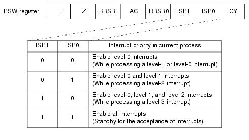
The RI78V4 uses the "ISP1" and "ISP0" bits in the PSW register to enable and disable interrupts. Set ISP1 to 0 and ISP0 to 1 to disable interrupts in the RI78V4. Set ISP1 to 1 and ISP0 to 1 to enable interrupts in the RI78V4.
The "IE" bit of the RI78V4's PSW register inherits the value of the service call or RI78V4-function issuer. EI and DI instructions do not manipulate the "IE" value. As exceptions, however, there are places in the RI78V4 where EI and DI instructions are used.
- Immediately before starting a task specifying interrupts as disabled, a DI instruction is used to set IE to 0.
- Immediately before starting a task specifying interrupts as enabled, an EI instruction is used to set IE to 1.
- Inside the __kernel_int_entry function, which performs interrupt handler start processing, IE is set to 1.
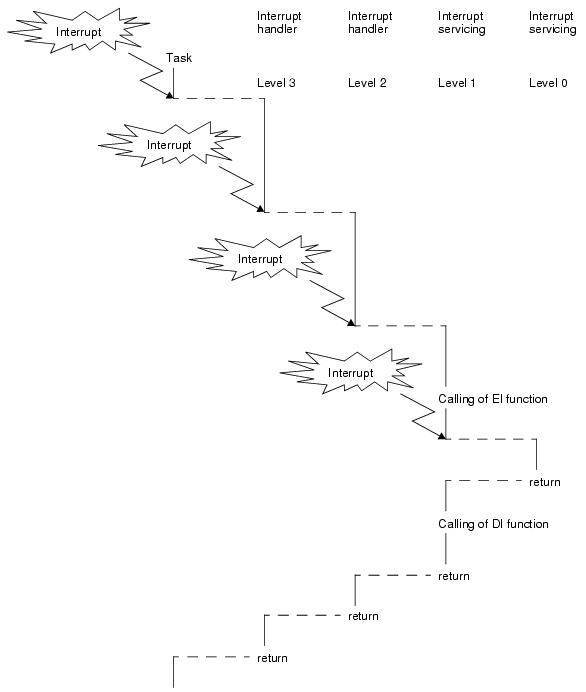
User applications use the EI function (or EI instruction) and DI function (or DI instruction) to manipulate interrupts. In a task or other user process, using the DI function disables all maskable interrupts from being accepted; using the EI function enables maskable interrupts to be accepted in accordance with the state of the "ISP1" and "ISP0" bits.
The RI78V4 sets whether interrupts are enabled or disabled upon start of the user process. The states are listed below.
Note that a separate "IE" state is maintained for each task. If a suspended task is resumed, the IE state before suspension is restored.
When control moves to an interrupt handler, then the state changes to acceptance of maskable interrupts enabled ("IE = 1"). For this reason, multiple interrupts are generally accepted from interrupt handlers. Multiple interrupts are likewise accepted from timer interrupts and cyclic handlers called from them.
When control moves to an interrupt process, then the state changes to acceptance of maskable interrupts disabled (because the RI78V4 does not mediate, the behavior is in accordance with that of the microcontroller). For this reason, multiple interrupts are generally not accepted from interrupt processes. To enable the acceptance of multiple interrupts, it is necessary to call the EI function from the interrupt process. It is not allowed to accept multiple interrupt handlers from an interrupt process, and behavior is not guaranteed if this occurs.
If a user application enables multiple interrupts, then it is necessary to set the interrupt level of the interrupt handler/process as shown below.
If a user application disables multiple interrupts, then it is necessary to set the interrupt level of the interrupt handler/process to one of the patterns shown below.
Pattern 3: Set the level of all interrupt handlers and to 2, and the level of all interrupt processes to either 2 or 3. Interrupts are disabled during an interrupt process with an interrupt level of 3 (IE = 0).


