CHAPTER 9 TIME MANAGEMENT FUNCTIONS
The RI850V4's time management function provides methods to implement time-related processing (Timer Operations: Delayed task wakeup, Timeout, Cyclic handlers) by using base clock timer interrupts that occur at constant intervals, as well as a function to manipulate and reference the system time.
After initialization by the Kernel Initialization Module, the system time is updated based on the Base clock interval: tim_base when an EI level maskable interrupt defined in the Base clock timer exception code: tim_intno in the system configuration file occurs.
To realize the time management function, the RI850V4 uses interrupts that occur at constant intervals (base clock timer interrupts).
When a base clock timer interrupt occurs, processing related to the RI850V4 time (system time update, task timeout/delay, cyclic handler activation, etc.) is executed.
A base clock timer interrupt is caused by an EI level maskable interrupt defined in the Base clock timer exception code: tim_intno in the system configuration file.
The RI850V4 does not initialize hardware to generate base clock timer interrupts, so it must be coded by the user.
Initialize the hardware used by Boot processing or Initialization routine and cancel the interrupt masking.
Note When passing control to the processing related to the base clock timer interrupt, the RI850V4 enables acceptance of EI level maskable interrupts by manipulating the PMn bits in the priority mask register (PMR) and the ID bit in the program status word (PSW), and issuing the eiret instruction (clearing the in-service priority register (ISPR)).
Therefore, if an EI level maskable interrupt occurs within the base clock timer interrupt processing, the interrupt is accepted.
Therefore, if an EI level maskable interrupt occurs within the base clock timer interrupt processing, the interrupt is accepted.
If is desirable to set 1 ms for the occurrence interval of base clock timer interrupts, but it may be difficult depending on the target system performance (processing capability, required time resolution, or the like).
The interval between occurrences of base clock timer interrupts can be defined as the Base clock interval: tim_base in the system configuration file.
By specifying the base clock cycle, processing regards that the time equivalent to the base clock cycle elapses during a base clock timer interrupt.
An integer value larger than 1 can be specified for the base clock cycle. Floating-point values such as 2.5 cannot be specified.
The RI850V4's timer operation function provides Delayed task wakeup, Timeout and Cyclic handlers, as the method for realizing time-dependent processing.
Delayed wakeup the operation that makes the invoking task transit from the RUNNING state to the WAITING state during the interval until a given length of time has elapsed, and makes that task move from the WAITING state to the READY state once the given length of time has elapsed.
Timeout is the operation that makes the target task move from the RUNNING state to the WAITING state during the interval until a given length of time has elapsed if the required condition issued from a task is not immediately satisfied, and makes that task move from the WAITING state to the READY state regardless of whether the required condition is satisfied once the given length of time has elapsed.
The cyclic handler is a routine dedicated to cycle processing that is activated periodically at a constant interval (activation cycle).
The RI850V4 handles the cyclic handler as a "non-task (module independent from tasks)". Therefore, even if a task with the highest priority in the system is being executed, the processing is suspended when a specified activation cycle has come, and the control is passed to the cyclic handler.
The RI850V4 handles the cyclic handler as a "non-task (module independent from tasks)". Therefore, even if a task with the highest priority in the system is being executed, the processing is suspended when a specified activation cycle has come, and the control is passed to the cyclic handler.
The RI850V4 manages the states in which each cyclic handler may enter and cyclic handlers themselves, by using management objects (cyclic handler control blocks) corresponding to cyclic handlers one-to-one.
- Basic form of cyclic handlers
When coding a cyclic handler, use a void function with one VP_INT argument (any function name is fine).
The extended information specified with Cyclic handler information is set for the exinf argument.
The following shows the basic form of cyclic handlers in C.
When coding a cyclic handler, use a void function with one VP_INT argument (any function name is fine).
The extended information specified with Cyclic handler information is set for the exinf argument.
The following shows the basic form of cyclic handlers in C.
- Coding method
Code cyclic handlers using C or assembly language.
When coding in C, they can be coded in the same manner as void type functions coded.
When coding in assembly language, code them according to the calling rules prescribed in the compiler used.
Code cyclic handlers using C or assembly language.
When coding in C, they can be coded in the same manner as void type functions coded.
When coding in assembly language, code them according to the calling rules prescribed in the compiler used.
- Stack switching
The RI850V4 switches to the system stack specified in the Basic information when passing control to a cyclic handler, and switches to the relevant stack when returning control from the cyclic handler to the processing program in which a base clock timer interrupt occurred and caused activation of the cyclic handler. Therefore, coding regarding stack switching is not required in a cyclic handler.
The RI850V4 switches to the system stack specified in the Basic information when passing control to a cyclic handler, and switches to the relevant stack when returning control from the cyclic handler to the processing program in which a base clock timer interrupt occurred and caused activation of the cyclic handler. Therefore, coding regarding stack switching is not required in a cyclic handler.
- Service call issue
The RI850V4 handles the cyclic handler as a "non-task".
Service calls that can be issued in cyclic handlers are limited to the service calls that can be issued from non-tasks.
The RI850V4 handles the cyclic handler as a "non-task".
Service calls that can be issued in cyclic handlers are limited to the service calls that can be issued from non-tasks.
Note 1 If a service call (isig_sem, iset_flg, etc.) accompanying dispatch processing (task scheduling processing) is issued in order to quickly complete the processing in the cyclic handler during the interval until the processing in the cyclic handler ends, the RI850V4 executes only processing such as queue manipulation, counter manipulation, etc., and the actual dispatch processing is delayed until a return instruction is issued by the cyclic handler, upon which the actual dispatch processing is performed in batch.
Note 2 For details on the valid issue range of each service call, refer to Table 16-1 to Table 16-12.
- Acceptance of EI level maskable interrupts
When passing control to a cyclic handler, the RI850V4 enables acceptance of EI level maskable interrupts by manipulating the PMn bits in the priority mask register (PMR) and the ID bit in the program status word (PSW), and issuing the eiret instruction (clearing the in-service priority register (ISPR)).
Therefore, if an EI level maskable interrupt occurs within a cyclic handler, the interrupt is accepted.
Cyclic handlers therefore cannot be created dynamically using a method such as issuing a service call from a processing program.
Static cyclic handler creation means defining of cyclic handlers using static API "CRE_CYC" in the system configuration file.
- set_tim, iset_tim
These service calls change the RI850V4 system time (unit: millisecond) to the time specified by parameter p_systim.
The following describes an example for coding this service call.
These service calls change the RI850V4 system time (unit: millisecond) to the time specified by parameter p_systim.
The following describes an example for coding this service call.
#include <kernel.h> /*Standard header file definition*/ #include <kernel_id.h> /*System information header file definition*/ void task (VP_INT exinf) { SYSTIM p_systim; /*Declares data structure*/ p_systim.ltime = 3600; /*Initializes data structure*/ p_systim.utime = 0; /*Initializes data structure*/ ......... set_tim (&p_systim); /*Set system time*/ ......... } |
The system time can be referenced by issuing the following service call from the processing program.
- get_tim, iget_tim
These service calls store the RI850V4 system time (unit: millisecond) into the area specified by parameter p_systim.
The following describes an example for coding this service call.
These service calls store the RI850V4 system time (unit: millisecond) into the area specified by parameter p_systim.
The following describes an example for coding this service call.
#include <kernel.h> /*Standard header file definition*/ #include <kernel_id.h> /*System information header file definition*/ void task (VP_INT exinf) { SYSTIM p_systim; /*Declares data structure*/ UW ltime; /*Declares variable*/ UH utime; /*Declares variable*/ ......... get_tim (&p_systim); /*Reference System Time*/ ltime = p_systim.ltime; /*Acquirer system time (lower 32 bits)*/ utime = p_systim.utime; /*Acquirer system time (higher 16 bits)*/ ......... } |
Note 1 The RI850V4 ignores the numeric values that cannot be expressed as the system time (values overflowed from the 48-bit width).
Moving to the operational state (STA state) is implemented by issuing the following service call from the processing program.
- sta_cyc, ista_cyc
This service call moves the cyclic handler specified by parameter cycid from the non-operational state (STP state) to operational state (STA state).
As a result, the target cyclic handler is handled as an activation target of the RI850V4.
The relative interval from when either of this service call is issued until the first activation request is issued varies depending on whether the TA_PHS attribute is specified for the target cyclic handler during configuration.
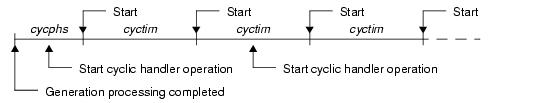
- If the TA_PHS attribute is specified
The target cyclic handler activation timing is set based on the activation phases (initial activation phase cycphs and activation cycle cyctim) defined during configuration.
If the target cyclic handler has already been started, however, no processing is performed even if this service call is issued, but it is not handled as an error.
The following shows a cyclic handler activation timing image.
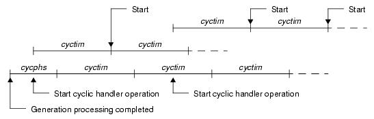
- If the TA_PHS attribute is not specified
The target cyclic handler activation timing is set based on the activation phase (activation cycle cyctim) when this service call is issued.
This setting is performed regardless of the operating status of the target cyclic handler.
The following shows a cyclic handler activation timing image.
The target cyclic handler activation timing is set based on the activation phase (activation cycle cyctim) when this service call is issued.
This setting is performed regardless of the operating status of the target cyclic handler.
The following shows a cyclic handler activation timing image.
#include <kernel.h> /*Standard header file definition*/ #include <kernel_id.h> /*System information header file definition*/ void task (VP_INT exinf) |
{ ID cycid = ID_CYC1; /*Declares and initializes variable*/ sta_cyc (cycid); /*Start cyclic handler operation*/ ......... } |
Note The extended information specified in the Cyclic handler information is passed to the cyclic handler activated by issuing this service call.
Moving to the non-operational state (STP state) is implemented by issuing the following service call from the processing program.
- stp_cyc, istp_cyc
This service call moves the cyclic handler specified by parameter cycid from the operational state (STA state) to non-operational state (STP state).
As a result, the target cyclic handler is excluded from activation targets of the RI850V4 until issue of sta_cyc or ista_cyc.
The following describes an example for coding this service call.
#include <kernel.h> /*Standard header file definition*/ #include <kernel_id.h> /*System information header file definition*/ void task (VP_INT exinf) { ID cycid = ID_CYC1; /*Declares and initializes variable*/ ......... stp_cyc (cycid); /*Stop cyclic handler operation*/ ......... } |
Note This service call does not perform queuing of stop requests. If this service call has already been issued and the target cyclic handler has been moved to the non-operational state (STP state), no processing is performed but it is not handled as an error.
- ref_cyc, iref_cyc
Stores cyclic handler state packet (current state, time left before the next activation, etc.) of the cyclic handler specified by parameter cycid in the area specified by parameter pk_rcyc.
The following describes an example for coding this service call.
Stores cyclic handler state packet (current state, time left before the next activation, etc.) of the cyclic handler specified by parameter cycid in the area specified by parameter pk_rcyc.
The following describes an example for coding this service call.
#include <kernel.h> /*Standard header file definition*/ #include <kernel_id.h> /*System information header file definition*/ void task (VP_INT exinf) { ID cycid = ID_CYC1; /*Declares and initializes variable*/ T_RCYC pk_rcyc; /*Declares data structure*/ STAT cycstat; /*Declares variable*/ RELTIM lefttim; /*Declares variable*/ ATR cycatr; /*Declares variable*/ RELTIM cyctim; /*Declares variable*/ RELTIM cycphs; /*Declares variable*/ ......... ref_cyc (cycid, &pk_rcyc); /*Reference cyclic handler state*/ cycstat = pk_rcyc.cycstat; /*Reference current state*/ lefttim = pk_rcyc.lefttim; /*Reference time left before the next */ /*activation*/ cycatr = pk_rcyc.cycatr; /*Reference attribute*/ cyctim = pk_rcyc.cyctim; /*Reference activation cycle*/ cycphs = pk_rcyc.cycphs; /*Reference activation phase*/ ......... } |
Note For details about the cyclic handler state packet, refer to "15.2.12 Cyclic handler state packet".