Everything
5.1.16 Operand characteristics

Instructions and directives requiring one or more operands differ in the size and address range of the required operand values of the operands.

For example, the function of the instruction "MOV r, #byte" is to transfer the value indicated by "byte" to register "r". Because the register is an 8-bit register, the data size of "byte" must be 8 bits or less.

An assembly error will occur at the statement "MOV R0, 0x100", because the value of the second operand (0x100) cannot be expressed with 8 bits.

Therefore, it is necessary to bear the following points in mind when describing operands.

-

Whether the size and address range are suitable for an operand of that instruction (numeric value, name, label)

(1)

Operand value sizes and address ranges

There are conditions that limit the size and address ranges of numeric values, names and labels used as instruction operands.

For instructions, the size and address range of operands are limited by the operand representation. For directives, they are limited by the directive type.

These limiting conditions are as follows.

Table 5.9

Instruction Operand Value Ranges

Operand Representation

Value Range

byte

8-bit value : 0x00 to 0xFF

word

word [B]

word [C]

word [BC]

-

Numeric constants

0x0000 to 0xFFFF

-

Labels

0xF0000 to 0xFFFFFNote 1

When a label is in the mirror source areaNote 2, the corresponding address in the mirror destination areaNote 2 is masked to be a 16-bit value and this value should be within the above range

ES : word [B]

ES : word [C]

ES : word [BC]

-

Numeric constants

0x0000 to 0xFFFF

-

Labels

0x00000 to 0xFFFFF

The ES value is not checked for its valid range

Other than the above

16-bit value : 0x0000 to 0xFFFF

saddr

0xFFE20 to 0xFFF1FNote 3

Note that the saddr area range depends on the device

saddrp

0xFFE20 to 0xFFF1F even numbeNote 3

Note that the saddr area range depends on the device

sfr

0xFFF20 to 0xFFFFF : Special function register symbols (SFR symbolsNote 4), numeric constants, and symbols

sfrp

0xFFF20 to 0xFFFFE : Special function register symbols (SFR symbolsNote 4), numeric constants, and symbols(even values only)

addr5

0x00080 to 0x000BF (CALLT table area, even values only)

addr16

!addr16

(BR, CALL instructions)

0x0000 to 0xFFFF

(The range in which numeric constants and symbols can be specified is the same)

!addr16Note 5

(Other than BR, CALL instructions)

-

Numeric constantsNote 6

0x0000 to 0xFFFF

-

LabelsNote 6

0xF0000 to 0xFFFFFNote 1

When a label is in the mirror source areaNote 2, the corresponding address in the mirror destination areaNote 2 is masked to be a 16-bit value and this value should be within the above rang

ES:!addr16

-

Numeric constantsNote 6

0x0000 to 0xFFFF

-

LabelsNote 6

0x00000 to 0xFFFFF

The ES value is not checked for its valid range

!addr16.bit

-

When addr16 is a numeric constant

0x0000 to 0xFFFF

-

When addr16 or addr16.bit is a label

0xF0000 to 0xFFFFFNote 1

When a label is in the mirror source areaNote 2, the corresponding address in the mirror destination areaNote 2 is masked to be a 16-bit value and this value should be within the above rang

ES : !addr16.bit

-

When addr16 is a numeric constant

0x0000 to 0xFFFF

-

When addr16 or addr16.bit is a label

0x00000 to 0xFFFFF

The ES value is not checked for its valid range

addr20

$addr20

0x00000 to 0xFFFFF, and when a branch destination is in the range (-0x80) to (+0x7F) from the next address after a branch instruction

$!addr20

0x000000 to 0xFFFFFF, and when a branch destination is in the range (-0x8000) to (+0x7FFF) from the next address after a branch instruction

!!addr20

0x00000 to 0xFFFFF

bit

3-bit value : 0 to 7

RBn

n:2-bit value : 0 to 3

Note 1.

The mirror destination area and the internal RAM area are the valid ranges, and the actual ranges of these areas are determined by referring to the device file. When the device file is not referred to, the valid range is 0xF0000 to 0xFFFFF.

Note 2.

The address range of the mirror source area differs depending to the device. For details, see the user's manual of the device.

Note 3.

The saddr area is determined by referring to the device file. When the device file is not referred to, the valid range is 0xFFE20 to 0xFFF1F.

Note 4.

The address range for SFR symbols is determined by referring to the device file. When the device file is not referenced, SFR symbols must not be used. The address range for SFR symbols is 0xFFF00 to 0xFFFFF, but the address range from 0xFFF00 to 0xFFF1F is regarded as saddr even if an SFR symbol is used.

Note 5.

When an SFR symbol or an extended SFR (2ndSFR) symbol is used as an operand, "!SFR" or "!2ndSFR" can be written as "!addr16" and a code for "!addr16" is generated.
The address range for extended SFR symbols is also determined by referring to the device file.

Note 6.

Only an even value is allowed for an operand in a 16-bit instruction (16-bit data transfer instruction or 16-bit operation instruction).


The range differs between numeric constants and labels for the following reason.

When a code is generated for operand "word" or "addr16", the range of the values that can be output is 0x0000 to 0xFFFF. Therefore, when a numeric constant is specified as an operand, it is checked for this range. However, when a label is specified as an operand, the range is determined as follows considering the meaning of each value.


(a)

word

The actual location to be accessed is 0xF0000 to 0xFFFFF in the based addressing. Therefore, a label is checked for this address range.

(b)

addr16

The actual location to be accessed is 0xF0000 to 0xFFFFF except for the BR and CALL instructions. Therefore, a label is checked for this address range.

Table 5.10

Value ranges of Directive Operands

Directive Type

Directive

Value Range

Section definition

.ORG

0x00000 to 0xFFFFF

.OFFSET

0x00000 to 0xFFFFF

Symbol definition

.EQU

0x00000000 to 0xFFFFFFFF

For a bit symbol, the range is as follows:

Address value : 0x00000 to 0xFFFFF

Bit value : 0 to 7

.SET

0x00000000 to 0xFFFFFFFF

Data definition/Area reservation

.DB

Initial value setting: 0x00 to 0xFF

.DB2

Initial value setting: 0x0000 to 0xFFFF

.DB4

Initial value setting: 0x00000000 to 0xFFFFFFFF

.DB8

Initial value setting: 0x00000000 00000000 to 0xFFFFFFFF FFFFFFFF

.DS

Size setting : 0x00000 to 0xFFFFF

.ALIGN

Alignment condition value : 2 or a greater even number less than 231

(2)

Sizes of operands required by instructions

Instructions can be classified into machine instructions and directives. When they require immediate data or symbols, the size of the required operand differs according to the instruction or directive. An error occurs when source code specifies data that is larger than the required operand.

Evaluation of an expression is done in 32 bits, both during calculation and for the calculation result. Therefore, even an overflow value is handled in 32 bits.

However, when a relocatable symbol is specified as an operand, its value cannot be determined by the assembler. In this case, the linker determines the value and checks its range.

(3)

Symbol attribute required by instructions

Among the instructions that allow a symbol to be specified as an operand, the attribute (absolute, relocatable, or external reference) of symbols that can be specified differ depending on the instruction.

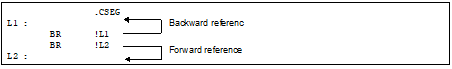
Reference direction for symbols can be backward reference or forward reference.

-

Backward reference : A symbol referenced as an operand, which is defined in a line above (before) the name or label

-

Forward reference : A symbol referenced as an operand, which is defined in a line below (after) the name or label


<Example>


The following shows the attributes of symbols that can be specified as operands for machine-language instructions.

Table 5.11

Properties of Described Symbols as Operands


Relocation Attributes

Attributes

Relocatable Note 1

SFR Reserved WordsNote 2

Reference Pattern

Backward

Forward

Backward

Forward

SFR

2ndSFRNote 3

Description Format

byte

OK

OK

OK

OK

-

-

word

OK

OK

OK

OK

-

-

saddr

OK

OK

OK

OK

OKNote 4,5

-

saddrp

OK

OK

OK

OK

OKNote 4,6

-

sfr

-

-

-

-

OKNote 4,7

-

sfrp

-

-

-

-

OKNote 4,8

-

addr20

OK

OK

OK

OK

OK

OK

addr16

OK

OK

OK

OK

OKNote 9

OKNote 9

addr5

OK

OK

OK

OK

-

-

bit

OK

-

-

-

-

-


Forward : Forward reference

Backward : Backward reference

OK : Description possible

- : An error

Note 1.

When a relocatable symbol is used, the optimizing linker determines its value and checks its range.

Note 2.

The defined symbol specifying sfr or sfrp (sfr area where saddr and sfr are not overlapped) as an operand of .EQU directive is only referenced backward. Forward reference is prohibited.

Note 3.

2nd SFR : 2nd Special Function Register

Note 4.

If an SFR symbols in the saddr area has been described for an instruction in which a combination of sfr/sfrp changed from saddr/saddrp exists in the operand combination, a code is output as saddr/saddrp.

Note 5.

8-bit SFR in saddr area

Note 6.

16-bit SFR in saddr area

Note 7.

8-bit SFR

Note 8.

16-bit SFR

Note 9.

!SFR, !2ndSFR, and SFR can be specified only for operand !addr16 of instructions other than BR and CALL.

Table 5.12

Properties of Described Symbols as Operands of Directives


Relocation Attributes

Attributes

Relocatable Note 1

Reference Pattern

Backward

Forward

Backward

Forward

Directive

.ORG

OK Note 2

-

-

-

.OFFSET

OK Note 2

-

-

-

.EQU

OK Note 2

-

-

-

.SET

OK Note 2

-

-

-

.DB

OK

OK

OK

OK

.DB2

OK

OK

OK

OK

.DB4

OK

OK

OK

OK

.DB8

OK Note 2

-

-

-

.DS

OK Note 2

-

-

-

.ALIGN

OK Note 2

-

-

-


Forward : Forward reference

Backward : Backward reference

OK : Description possible

- : Description impossible

Note 1.

When a relocatable symbol is used, the optimizing linker determines its value and checks its range.

Note 2.

Only an absolute expression can be described.