|


|
Light Emitting Diode
An LED can be connected to any pin, and the output from the pin can be indicated by switching the LED on or off.
|
|


(with brightness control)
|
Light Emitting Diode
An LED can be connected to any pin, and PWM control can be used to control the apparent brightness by switching the LED on and off.
The display on the LED is not correct if the PWM cycle is greater than 100 ms.
|
|


|
Digital input switch (push type)
A button can be connected to any pin. A digital input value can be given to the connected pin by clicking the displayed button.
|
|


|
Digital input switch (toggle type)
A button can be connected to any pin. A digital input value can be given to the connected pin by clicking the displayed button.
|
|

|
Used for inputting analog data. Any data within a given range can be set.
Any value within a specified range can be assigned to a pin connected to an A/D converter.
|
|


|
Used for inputting analog data. Any data within a given range can be set.
The gas concentration sensor value (PPM) is converted to a voltage for a pin connected to. Any value within a specified range can be assigned to the pin.
|
|

|
Used for inputting analog data. Any data within a given range can be set.
The current value (mA) is converted to the voltage for the connected pin. Any value within a specified range can be assigned to the pin.
|
|


|
Used for inputting analog data. Any data within a given range can be set.
The illuminance (lux) is converted to a voltage for the connected pin.
Any value within a specified range can be assigned to the pin.
|
|


|
Switch for vibration sensing
A button can be connected to any pin. A digital input value can be given to the connected pin by clicking the displayed button.
|
|


|
Buzzer for an alarm machine
A button can be connected to any pin. The output of the pin is indicated by both sound and image.
|
|


|
Temperature sensor
The voltage produced from the specified temperature can be applied to a pin to which the A/D converter is connected.
Relational expression between temperature and input voltage:
Voltage (V) input to the connected pin =
(conversion_factor[mV/℃] x specified_temperature[℃] + conversion_offset[mV]) / 1000.0
|
|

|
Fan motor
The fan is made to rotate by the input of a digital signal from the connected pin.
The rotational velocity can be controlled by the duty ratio of the PWM signal.
|
|

|
DC motor
The motor is made to rotate by the input of a digital signal from the connected pin.
The rotational velocity can be controlled by the duty ratio of the PWM signal.
|
|


|
Shading sensor
A specified voltage value can be output to the connected pin in response to covering the red light-emitting part by the hand-image icon.
|
|


|
Wireless-charging transmitter
When a PWM signal is being input through the connected pin, a sphere revolves around the component to indicate that charging is in progress.
|
|


|
Infrared receiver
Clicking on the component leads to the output of the signal which has been specified for the connected pin.
|
|
|
Segment LCD for internal driverNote1
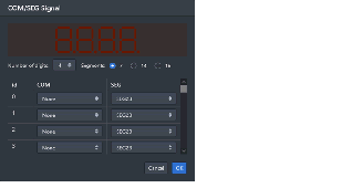
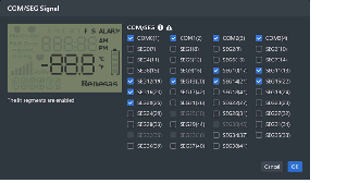
Segments of this LCD are illuminated in response to control signals sent from the LCD driver in the MCU. You can control the correspondence between the MCU's control signals and segments in the property area.
|
|

|
7-segment LEDs for displaying up to eight-digit numbers with dynamic lighting.
|
|

|
Brushless DC motorNote2
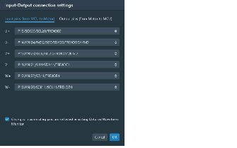
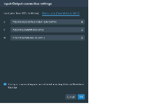
Signals output from the component are used in control by a feedback system. When a three-phase PWM signal is input, the motor rotates.
|
|

|
Used for specifying multiple switches for an analog input pin.
A maximum of five switches are specifiable.
When a switch is pressed, the voltage specified for the given switches is input to the selected analog pin.
|
|

|
RSK LCD Panel
An LCD panel included with the Renesas Starter Kit for RL78/L12Note3, which operates with the on-chip LCD controller of that MCU.
|
|

|
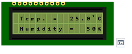
Character LCDs that operate with GPIO connections, one having a display area with two lines of eight characters and the other two lines of 16 characters.
|
|

|
A console used for UART communications with the MCU. The transmitted or received data can be confirmed in the Serial Monitor tab.
The serial monitoring area can also be opened by clicking on the icon button at the bottom right corner of the component.
|
|

|
Connected to the MCU via the UART to operate as a mock-up component for Wi-Fi communications.
When a command is received from the MCU via the UART, a defined response is returned. The transmitted or received data can be confirmed in the Serial Monitor tab.
The serial monitoring area can also be opened by clicking on the icon button at the bottom right corner of the component.
|
|

|
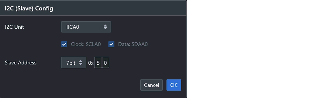
A character-LCD component for displaying data through I2C communications.
The component has a display area with two lines of 16 characters.
Details of the I2C communications can be confirmed on the Serial Monitor tab. The serial monitoring area can also be opened by clicking on the console icon button at the bottom right corner of the component.
The register values in the component can be confirmed by clicking on the table icon button next to the center-right side of the component.
|
|

|
A device for sending and receiving data through I2C communications. The register values in the component can be changed to the desired values.
Details of the I2C communications can be confirmed on the Serial Monitor tab. The serial monitoring area can also be opened by clicking on the console icon button at the bottom right corner of the component.
The register values in the component can be confirmed by clicking on the table icon button next to the center-right side of the component.
|
|

|
A component representing the operation of a fire detector that consists of an infrared LED, photodiode, and operational amplifier. If a fire is detected, it produces current for input to an analog input pin.
|
|

|
A component for the input of a cyclic pulse signal.
|
|

|
A component consisting of an RS-485 transceiver connected to the MCU via a UART and a Modbus communications device.
Details of the I2C communications can be confirmed on the Serial Monitor tab. The serial monitoring area can also be opened by clicking on the console icon button at the bottom right corner of the component.
|
|
|
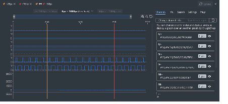
Connected to the MCU via the UART to operate as a mock-up component for MQTT communications via LTE.
When a command is received from the MCU via the UART, a defined response is returned.
The transmitted or received data can be confirmed in the Serial Monitor tab.
The serial monitoring area can also be opened by clicking on the icon button at the bottom right corner of the component.
|
|
|
This component has switches arranged in a grid pattern and can determine whether a switch is ON or OFF with a small number of input/output pins.
|
|
|
It is connected to the MCU via UART and operates as a mock for TCP communication via Wi-Fi. When a command is received from the MCU via the UART, a defined response is returned.
The transmitted or received data can be confirmed in the Serial Monitor tab. The serial monitoring area can also be opened by clicking on the icon button at the bottom right corner of the component.
|
|
|
This component can input digital signals transmitted by infrared remote control to the input pin. The repeat function is not supported when the button is pressed and held.
|
|
|
This sensor measures the distance to an object using the reflection time of ultrasonic waves. When a trigger pulse is input, a reflection time signal is output according to the distance to the object.
|
|

|
Power LED with constant current control.
|
|
|
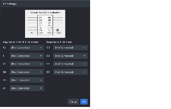
This component can display 14-segment and 8-digit numbers by connecting to an MCU with an internal LCD driver.Note1
|
|
|
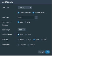
This component is connected to the MCU via UART and sends and receives MIDI messages.
|
|
|
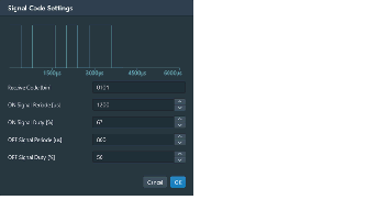
This is a component that receives infrared signals transmitted by an infrared remote control and decodes them according to a specified format.
|
|
|
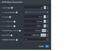
This is a component that allows you to individually control multiple LEDs using a single signal line.
|
|
|
This is an RGB LED matrix module with an 8x8 pixel configuration that can be controlled via SPI communication.
|