2.11.1.4
Displaying and changing memory contents during program execution
The Memory panel and Watch panel come with a realtime display update function that permits you to update display of, or even rewrite, the contents of memory or watch-expressions in real time.
By enabling this realtime display update function, it is possible to display or change the values of memory or watch-expressions even while the program is running, not just when the program is halted.
Caution 1. | [E20(JTAG)[RX600 Series]]
The trace function and the real-time RAM monitor function (RRM function) in part are usable exclusively of each other. Therefore, before making the settings below, you must finish the following settings on the [Debug Tool Settings] tab of the Property panel in order to specify the function to be used preferentially.
- [Trace] category >> [Usage of trace function] properties >> [Real-time RAM Monitor] |
Caution 2. | [E20(JTAG)[RX600 Series]]
If a reset e.g. input of a reset signal through the reset pin, or reset of the CPU by the watchdog timer) is issued while a user program is running, the results of the real-time RAM monitor cannot be guaranteed (values displayed may be incorrect). |
Caution 3. | [E20]
To use the real-time RAM monitor function, the E20 and the target board must be connected via a 38-pin cable. The real-time RAM monitoring facility is not usable when the E20 and the target board are connected via a 14-pin cable. |
Remark | The real-time display update function is materialized by the debug tool's RRM (real-time RAM monitor), pseudo-RRM, and DMM (dynamic memory modification) functions.
The pseudo-RRM function temporarily momentarily breaks program execution to perform reads/writes by means of software emulation. |
The subject area to and from which you can write and read using the realtime display update function varies depending on how the debug tool you use and the Property panel are set.
Referring to the set contents of respective properties in the [Access Memory While Running] and [Trace] categories on the [Debug Tool Settings] tab of the Property panel shown below, make settings in Table 2.8 through Table 2.10 according to the purpose of use of the realtime display update function.
Table 2.8 | Subject Area of the Real-Time Display Update Function (Read by Pseudo-RRM Function) |
|
|
|
|
|
|
|
Internal ROM
|
C+D
|
Entire range
|
|
Internal RAM
|
|
Data flash
|
|
Target memory
|
|
Emulation memory
|
|
|
CPU register
|
|
|
I/O register
|
|
|
Table 2.9 | Subject Area of the Real-Time Display Update Function (Read by RRM Function) |
|
|
|
|
|
|
|
|
|
|
Internal ROM
|
A+B+D
|
Automatic setting area Note
|
D
|
Entire range
|
|
Internal RAM
|
|
Data flash
|
|
|
Target memory
|
|
Emulation memory
|
|
D
|
Entire range
|
|
CPU register
|
|
|
|
I/O register
|
|
Automatic setting area Note
|
D
|
Entire range
|
Note | [E20(JTAG) [RX600, RX700 Series]]
The subject area of the RRM function is limited to a maximum of 4,096 bytes (4 areas each containing maximum 1024 bytes).
Therefore, CS+ automatically determines the subject of realtime display updates within the above limit according to the determination rules (order of priority) shown below. (Only the panel that is displayed in front of others immediately before program execution becomes the subject.)
(1) Watch-expressions displayed on Watch panel are set in order from the top. (If multiple Watch panels are open, they are set in increasing order of panel number.)
(2) Memory contents displayed on Memory panel are set in increasing order of address. (If multiple Memory panel are open, they are set in increasing order of panel number.)
Note that if the subject area includes a read-prohibited area, display of that area is not updated. |
Table 2.10 | Subject Area of the Real-Time Display Update Function (Write by DMM Function) |
|
|
|
|
|
|
|
|
|
|
|
|
|
Internal ROM
|
|
|
D
|
Entire range
|
|
Internal RAM
|
C+D
|
Entire range
|
|
Automatic setting area Note
|
|
Data flash
|
|
|
|
|
Target memory
|
C+D
|
Entire range
|
|
Automatic setting area Note
|
|
Emulation memory
|
|
|
D
|
Entire range
|
|
CPU register
|
|
|
|
|
I/O register
|
C+D
|
Entire range
|
|
Automatic setting area Note
|
D
|
Entire range
|
Note | [E20(JTAG) [RX600, RX700 Series]]
The target area of the DMM function is the same as the target area of the RRM function. |
Caution | Local variables are not the subject of the real-time display update function. |
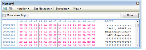
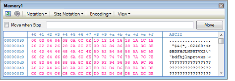
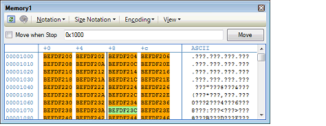
The memory values/watch-expressions updated by the pseudo-RRM function are highlighted in pink on the Memory panel, whereas those updated by the RRM function are highlighted as follows in accordance with the access status.
(The font and background colors depend on the configuration in the [General - Font and Color] category of the Option dialog box.
|
|
|
|
Read or fetch
|

|
|
Write
|

|
|
Read and Write
|

|
|
LostNote
|

|
Note | The watch-expression value will be displayed as "?" in the event of "Lost" on the Watch panel. |
Figure 2.103 | Example of Memory Display by the Pseudo-RRM Function (Memory Panel) [E1] [E20] |
Figure 2.104 | Example of Memory Display by the RRM Function (Memory Panel) [Simulator] |
Figure 2.105 | Example of Memory Display by the RRM Function (Memory Panel) [E20 (JTAG) [RX600 Series] |


