|
Parts Led Properties dialog box
|
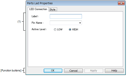
This property dialog box is used to set or change the pin connection information of LED, which are one of the connection parts in the I/O Panel window.
A pin-connected LED displays the information output from the simulator through lit/unlit display in the Simulation mode.
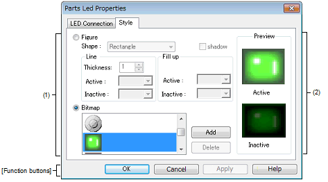
There are two types of LED display styles, figure and bitmap. These styles can be changed on the [[Style] tab].
Figure A.75 | Parts Led Properties Dialog Box: [LED Connection] Tab |
Figure A.76 | Parts Led Properties Dialog Box: [Style] Tab |
This section describes the following.
[How to open]
On the I/O Panel window, any one of the following:
- | Double-click a part object "LED". |
- | Select [Properties...] form the context menu on a part object "LED". |
- | Select a part object "LED", and then select [Properties...] form the [View] menu. |
[[LED Connection] tab]
(1) | Pin connection information setting area |
|
Label
|
This area is used to specify the part name. The part name input here is also displayed in the Parts List dialog box as the label.
|
|
Pin Name
|
This area is used to specify the pin name to be connected (output pin). The connection pins can be specified either via direct input or through selection from the drop-down list.
|
|
Active Level
|
The active state is selected with a option button, as follows:
|
|
LOW
|
Sets the active level to LOW.
|
|
HIGH
|
Sets the active level to HIGH (default).
|
Remark | For the pin names that can be specified, see the user's manual of the microcontroller that is used. |
[[Style] tab]
(1) | Style information setting area |
|
Figure
|
Select this option button to display the LED with the following specified figure.
|
|
Shape
|
Select the figure shape. Two shapes can be selected: rectangle and ellipse.
|
|
shadow
|
Cannot be selected.
|
|
Line
|
Specify and change the figure line, as follows.
You can change the color of figure line by clicking the pull-down button.
|
|
Thickness
|
Specifies the line thickness.
Specification is made either using a spin button or through direct input.
A value from 1 to 100 can be specified.
|
|
Active
|
Specifies the color of the line during active display.
|
|
Inactive
|
Specifies the color of the line during inactive display.
|
|
Fill up
|
Specify and change the figure filling, as follows.
You can change the color of figure filling by clicking the pull-down button.
|
|
Active
|
Specifies the fill color during active display.
|
|
Inactive
|
Specifies the fill color during inactive display.
|
|
Bitmap
|
Select this option button to display the LED with the following specified bitmap (default).
|
|
Selection list
|
Select a bitmap to be used from the selection list.
The selectable bitmaps appear in the selection list.
|
|
[Add] button
|
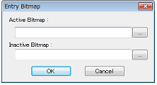
Opens the Entry Bitmap dialog box below to add a new bitmap to the selection list.
The bitmap file to be added can be specified either through file selection using the [...] button, or through direct input.
|
|
[Delete] button
|
Deletes the currently selected bitmap from the selection list.
Note that only the bitmap that have been added by user can be deleted.
|
This area displays the style of the LED currently being specified.
[Function buttons]
|
|
|
|
OK
|
Validates the settings and closes this dialog box.
|
|
Cancel
|
Cancels the settings and closes this dialog box.
|
|
Apply
|
Cannot be selected.
|
|
Help
|
Displays the help for this dialog box.
|
[Operation]
In the Simulation mode, the output status (active/inactive) of the connected pins is displayed in real-time using two types of bitmaps or figures.
Figure A.77 | Connected Parts Display Example (LED) |


