|
Virtual Board panel [Simulator]
|
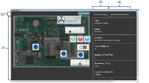
This panel is used to configure the virtual target system and operate the virtual components.
With this panel, the results of data that have been input to and output from peripheral I/O modules can be confirmed.
Note that this panel is only available when the simulator for the active project supports peripheral function simulations.
Figure A.50 | Virtual Board panel [Simulator] |
This section describes the following.
[How to open]
- | From the [View] menu, select [Virtual Board]. |
[Description of each area]
This area is used to operate the virtual target system.
It supports the following components.
These components can be operated while the program is running.
|

|
Light Emitting Diode
An LED can be connected to any pin, and the output from the pin can be indicated by switching the LED on or off.
|
|
 (with brightness control)
|
Light Emitting Diode
An LED can be connected to any pin, and PWM control can be used to control the apparent brightness by switching the LED on and off.
The display on the LED is not correct if the PWM cycle is greater than 100 ms.
|
|


|
Digital input switch (push type)
A button can be connected to any pin. A digital input value can be given to the connected pin by clicking the displayed button.
|
|


|
Digital input switch (toggle type)
A button can be connected to any pin. A digital input value can be given to the connected pin by clicking the displayed button.
|
|

|
Used for inputting analog data. Any data within a given range can be set.
Any value within a specified range can be assigned to a pin connected to an A/D converter.
|
|

|
Used for inputting analog data. Any data within a given range can be set.
The gas concentration sensor value (PPM) is converted to a voltage for a pin connected to. Any value within a specified range can be assigned to the pin.
|
|


|
Switch for vibration sensing
A button can be connected to any pin. A digital input value can be given to the connected pin by clicking the displayed button.
|
|


|
Buzzer for an alarm machine
A button can be connected to any pin. The output of the pin is indicated by both sound and image.
|
|

|
Temperature sensor
The voltage produced from the specified temperature can be applied to a pin to which the A/D converter is connected.
Relational expression between temperature and input voltage:
Voltage (V) input to the connected pin =
(conversion_factor[mV/℃] x specified_temperature[℃] + conversion_offset[mV]) / 1000.0
|
|

|
Fan motor
The fan is made to rotate by the input of a digital signal from the connected pin.
The rotational velocity can be controlled by the duty ratio of the PWM signal.
|
|

|
DC motor
The motor is made to rotate by the input of a digital signal from the connected pin.
The rotational velocity can be controlled by the duty ratio of the PWM signal.
|
|


|
Shading sensor
A specified voltage value can be output to the connected pin in response to covering the red light-emitting part by the hand-image icon.
|
|


|
Wireless-charging transmitter
When a PWM signal is being input through the connected pin, a sphere revolves around the component to indicate that charging is in progress.
|
|


|
Infrared receiver
Clicking on the component leads to the output of the signal which has been specified for the connected pin.
|
|

|
8x8 Segments LCD for internal driverNote1
Segments of this LCD are illuminated in response to control signals sent from the LCD driver in the MCU. You can control the correspondence between the MCU's control signals and segments in the property area.
|
|

|
Brushless DC motorNote2
Signals output from the component are used in control by a feedback system. When a three-phase PWM signal is input, the motor rotates.
|
|

|
Used for specifying multiple switches for an analog input pin.
A maximum of five switches are specifiable.
When a switch is pressed, the voltage specified for the given switches is input to the selected analog pin.
|
|

|
RSK LCD Panel
An LCD panel included with the Renesas Starter Kit for RL78/L12Note1, which operates with the on-chip LCD controller of that MCU.
|
|

|
RL78/Gx RSK LCD Panel
An LCD panel for debugging included with the Renesas Starter Kit for RL78/G13, G14.Note3
The panel has a display area with two lines of eight characters.
|
Note 1. | At present, this component is only available for use with devices of the RL78/L12 group. |
Note 2. | At present, this component is only available for use with devices of the RL78/G1F group. |
Note 3. | At present, this component is only available for use with devices of the RL78/G13, G13A, and G14 groups. |
These buttons are used to add components.
This area is valid while the program is stopped.
|
Add component
|
Clicking on the button displays a list of components which are available to be selected for addition.
Drag the component to move it to the position where it is to be placed.
Clicking on the delete button in the upper-right corner of the selected component deletes that component.
|
This area is used to display or edit the properties of the component.
The properties of the component selected while the program is stopped are displayed.
The following items are displayed in this area.
|
Type
|
Select the part.
|
|
Subtype
|
Select an LED with or without brightness control.
This property is displayed when the component is an LED.
|
|
LED without Brightness Control
|
The LED is turned on or off.
|
|
LED with Brightness Using PWM
|
The LED has brightness control.
|
|
Name
|
Specify the name of the part.
|
|
Connected to
|
Select the name of the pin to which the LED is to be connected.
|
|
Color
|
Select the color of the LED.
This property is displayed when the component is an LED.
The following colors can be selected.
Red, green, blue
|
|
Active Level
|
Select the active state.
This property is displayed when the component is an LED or switch.
|
|
Active High
|
Sets the active level to High.
|
|
Active Low
|
Sets the active level to Low.
|
|
Appearance
|
Select the type of the switch.
This property is displayed when the component is a switch.
|
|
Push
|
Sets the push switch.
|
|
Toggle
|
Sets the toggle switch.
|
|
Min Input Value
|
Display or specify the lower limit of an input value.
This property is displayed when the component is a potentiometer, a gas sensor, or a temperature sensor.
For a temperature sensor, the minimum input value is automatically calculated from the conversion factor and the conversion offset (- conversion_offset[mV] / conversion_factor[mV/℃]).
|
|
Max Input Value
|
Display or specify the upper limit of an input value.
This property is displayed when the component is a potentiometer, a gas sensor, or a temperature sensor.
For a temperature sensor, the maximum input value are automatically calculated from the following formula.
(max_input_voltage[V] - conversion_offset[mV] / 1000.0) / (conversion_factor[mV/℃] / 1000.0)
|
|
Input Step
|
Display or specify the minimum size of the variation in an input value.
This property is displayed when the component is a potentiometer, a gas sensor, or a temperature sensor.
For a potentiometer, the value displayed or entered in the text box is the stepping width.
|
|
Initial Input Value
|
Select the initial value when the CPU is reset.
This property is displayed when the component is a potentiometer, a gas sensor, or a temperature sensor.
|
|
On Reset
|
Select the operation when the CPU is reset.
This property is displayed when the component is a potentiometer, a gas sensor, or a temperature sensor.
|
|
Hold
|
The state immediately before the CPU was reset is retained after the CPU has been reset.
|
|
Initialize
|
Specify the value which has been selected in [Initial Input Value] when the CPU is reset.
|
|
Sound
|
Select the mute of the buzzer.
This property is displayed when the component is a buzzer.
|
|
Conversion Factor
|
Specify a factor for the conversion of each input value to a voltage value.
This property is displayed when the component is a gas sensor or a temperature sensor.
|
|
Conversion Offset
|
Specify an offset for the conversion of each input value to a voltage value.
This property is displayed when the component is a temperature sensor.
|
|
Max Input Voltage [V]
|
Specify the maximum voltage value that can be input to the connected port.
|
|
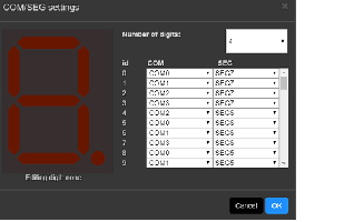
COM/SEG Signal
|
- | 8x8-segment LCD for use with the on-chip driver |
View or change the current settings of control signals to be sent to the 8x8-segment LCD for use with the on-chip driver.
This property initially shows the current setting for the number of digits and whether the control signals have been selected.
Selecting this property produces a button in the displayed area.
Clicking on the button brings up the control interface shown below.
Enter the desired number of digits and select the control signals for the individual segments. Click on the [OK] button to complete the settings.
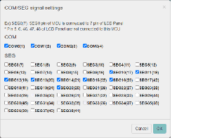
View or change the current settings for control signals to be sent to the LCD panel of the RSK.
Selecting this property brings up the control interface shown below.
Select the COM and SEG signals to be connected to the LCD panel. Click on the [OK] button to complete the settings.
|
|
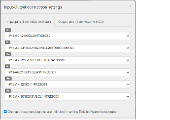
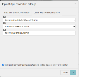
Input OutPut connection
|
View or change the current settings for the input and output pins to be used with the brushless DC motor.
Selecting this property produces a button in the displayed area.
Clicking on the button brings up the control interface shown below.
|
|
Switches
|
View or set the number of analog input switches and the voltages for the switches. Selecting this property shows a box for entering the voltage, an [Add] button, and tags for the voltages for the individual switches in the display area.
A switch with the voltage specified in the box for entering the value is added by pressing the [Add] button.
The voltages of individual switches are deleted by clicking on the [Delete] button of the tag.
|
|
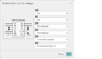
Pin Settings
|
View or change the current settings for control signals to be sent to the LCD panel of the RL78/Gx RSK.
Selecting this property brings up the control interface shown below.
Select six pins to be connected to the LCD panel. Click on the [OK] button to complete the settings.
|
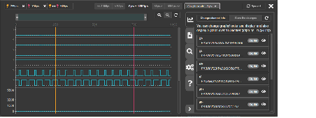
(4) | Detailed waveform monitoring area |
Clicking on the tab shows the detailed waveform monitor.
This monitor displays the waveforms of pins registered beforehand at 500-ns intervals for one millisecond before execution of the program is stopped.
In addition, markers can be used to check the states at particular points and a search function can be used to check whether combinations of states that satisfy certain conditions are present.
For details, refer to the part of the help system that can be displayed from the detailed waveform monitor.
Figure A.51 | Detailed waveform monitoring |
Caution | At present, this component is only available for use with devices of the RL78/G1F group. |
The Virtual Board Panel may use the copyrighted components specified in the file below.
CS+ install folder\CC\vboard\licenses-abstract.txt

 (with brightness control)


