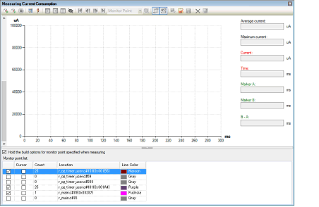
Measurement of current consumption refers to measuring the amount of current consumption by a whole system to be debugged.
In using the E2 emulator to measure current consumption, the current values in the target system as a whole are measured.
For measurement of current consumption, the facility for supplying power to the target by the E2 emulator and the E2 expansion interface are used.
Accordingly, to use this facility, be sure to specify [Yes] for the [Power target from the emulator (MAX 200mA)] property and [Use supplied power from the emulator] for the [Interface for supplying the power] property on the [Connect Settings] tab in the Property panel before connecting the debug tool.
Select [RX E2] as the debug tool, open the Solution List panel, and click on the [GO] button for measuring current consumption. The Measuring Current Consumption panel [E2] will open.

In measuring current consumption, you can acquire the pattern of transitions for the current value to be detected by setting conditions in advance. The main settings that can be made in advance are measurement conditions, trigger conditions, and monitoring points.
Operation after record memory is full: Overwrite to the record memory and continue execution
If you only want to measure the current as a trial, start the procedure from "(3) Start measurement".
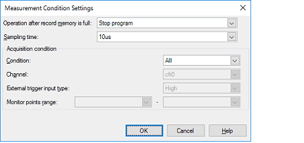
Set conditions regarding the recording of the measured current values in the Current Consumption Measurement Condition Setting dialog box [E2] which is displayed by clicking on  on the toolbar in the Measuring Current Consumption panel [E2].

Select any operation from among the following after the memory used to record the current values in the E2 emulator becomes full.
Select the sampling time for use in measurement from among the following.
1us, 2us, 5us, 10us, 20us, 50us, 100us, 200us, 500us, 1ms
An acquisition condition for recording the current values in the memory of the E2 emulator can be set so that recording only starts when the specific condition has been satisfied.
The condition can be selected as one of the following.
Record all current values that have been sampled after starting measurement without specifying specific conditions.
This item selects recording in memory in response to the external trigger input facility of the E2 expansion interface only while the specified signal is being detected.
When this is specified, the channel for input of the external trigger to be detected and the level of the signal to be detected must be specified.
In addition, the external trigger input must have been correctly set before the debug tool is connected.
For details on setting the external trigger input facility of the E2 expansion interface, refer to the Application Note on the Current Consumption Tuning Solution (E2 Emulator, CS+). |
Specify the monitoring point to serve as the start condition in the left entry field and that to serve as the end condition in the right entry field against [Monitor points range].
The current values will be recorded from detection of the monitoring point specified as the start condition until detection of the monitoring point specified as the end condition.
For details on the monitoring points, refer to "(c) Set monitoring points".
The E2 emulator is able to stop the program or output an external trigger signal in response to the value for current being measured satisfying a specific condition.
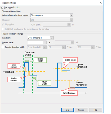
Set the trigger condition in the Current Consumption Measurement Trigger Condition Setting dialog box [E2], which is displayed by clicking on  on the toolbar in the Measuring Current Consumption panel [E2].

Select the checkbox for [Use trigger function] to use the trigger facility.
This checkbox is de-selected by default.
Select the operation when a trigger is detected as either of the following.
Stop execution of the program.
Output an external trigger through the E2 expansion interface.
Also make the following settings if an external trigger is to be output.
Specify the channel for output of the external trigger through the E2 expansion interface.
Select whether a high pulse is to be output in response to the condition being satisfied or output of the high level is to continue as long as the condition is being satisfied.
When a high pulse is to be output, also specify the pulse width.
For details on the external trigger output facility, refer to the Application Note on the Current Consumption Tuning Solution (E2 Emulator, CS+). |
Select the trigger condition for the current value as [Over Threshold], [Under Threshold], [In Range], or [Out of Range].
Specify the current value or range of current values to be detected as the trigger.
For a range of current values, the value entered in the left field for entry must be lower than that in the right field. |
As well as the condition for the current value, a sub-condition (condition for the detection width) regarding the time over which the condition is satisfied can be set. Specifying a width for detection can eliminate the detection of noise that temporarily satisfies the condition.
The condition for the detection width is selectable as [Over threshold] (detecting the current value when the condition continues to be satisfied for more than a specified time) or [In range] (detecting the current value when the condition is satisfied over a time within the specified range).
Specify a multiple of the sampling time as the detection width.
Note that the actual time for detection also depends on the sampling time.
A monitoring point is a facility for recording a timestamp when a specified line of source code is run.
When monitoring points are set, transitions of the execution time and the current values at the monitoring points can be confirmed on a graph for measuring current consumption.
The monitoring points are indicated by colored vertical lines on the graph.

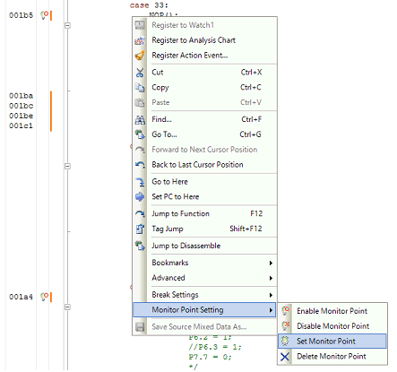
Monitoring points are set from [Monitor Point Setting] in the context menu after placing the cursor on the line of the target source code that was opened in the Editor panel.

A list of the monitoring points that are currently set is displayed under the Measuring Current Consumption panel [E2].
The monitoring points that have been set are enabled or disabled by the leftmost checkbox in this list or from the context menu of the Editor panel.

In the following cases, the monitoring points cannot be set when measurement starts, so that they are forcibly disabled. |
When monitoring points are set at instructions other than NOP instructions or the debug tool cannot detect the NOP instruction even if it is set as a monitoring point |
In the [System] category on the [Debug Tool Settings] tab in the Property panel, when [Yes] is selected either for the following properties: |
Monitoring points must be set at the addresses of NOP instructions. |
Start measuring current consumption by the target system by using the facilities of the E2 emulator.
Click on  or
or  on the toolbar in the Measuring Current Consumption panel [E2].

Current consumption is not measured by clicking on |
The project is rebuilt and downloaded before measurement starts.
However, if the device does not support monitoring points or the compiler used in the active project is a version of CC-RX earlier than V2.08.00, rebuilding and downloading do not proceed.
When [Hold the build options for monitor point specified when measuring] in the Measuring Current Consumption panel [E2] is selected, the options which are specified for rebuilding and downloading before measurement are reflected in the [Parameters of NOP instruction insertion for measuring current consumption] property of the build tool.
The project is not rebuilt and downloaded before measurement starts.
Select this button when you want to measure current consumption without resets due to rebuilding and downloading.
Note that this button is not displayed if the device does not support monitoring points or the compiler used in the active project is a version of CC-RX earlier than V2.08.00.
Measurement ends at the same time as execution of the program is stopped.
Execution of the program can be stopped by setting a breakpoint or a trigger condition, or by clicking on  .
.
At the same time as measurement ends, a graph of current values showing the results of measurement is displayed in the graph display area of the Measuring Current Consumption panel [E2].
Check that the current values that are shown are as intended.
In the panel, dragging a cursor (the red vertical line) shows the time and the current value at the cursor location in the information display area.
When the search facility is used, since the cursor is moved to the location where the search condition was satisfied, the time and the current value at that location can be confirmed.
Markers A and B (green vertical dashed lines) can also be dragged to confirm the average current and maximum current between the markers.
When a monitoring point is the target of the search, the location where processing to be confirmed was executed can be identified immediately.
 in the
