This panel is used to configure the virtual target system and operate the virtual components.
With this panel, the results of data that have been input to and output from peripheral I/O modules can be confirmed.
Note that this panel is only available when the simulator for the active project supports peripheral function simulations.
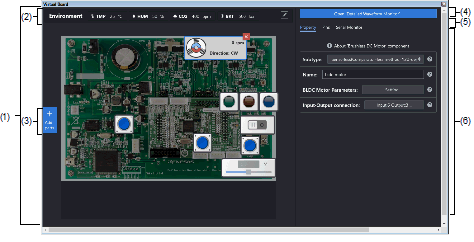
This section describes the following.
This area is used to operate the virtual target system.
It supports the following components.
These components can be operated while the program is running.
|
An LED can be connected to any pin, and the output from the pin can be indicated by switching the LED on or off. |
|
|
An LED can be connected to any pin, and PWM control can be used to control the apparent brightness by switching the LED on and off. The display on the LED is not correct if the PWM cycle is greater than 100 ms. |
|
|
Digital input switch (push type) A button can be connected to any pin. A digital input value can be given to the connected pin by clicking the displayed button. |
|
|
Digital input switch (toggle type) A button can be connected to any pin. A digital input value can be given to the connected pin by clicking the displayed button. |
|
|
Used for inputting analog data. Any data within a given range can be set. Any value within a specified range can be assigned to a pin connected to an A/D converter. |
|
|
Used for inputting analog data. Any data within a given range can be set. The gas concentration sensor value (PPM) is converted to a voltage for a pin connected to. Any value within a specified range can be assigned to the pin. |
|
|
Used for inputting analog data. Any data within a given range can be set. The current value (mA) is converted to the voltage for the connected pin. Any value within a specified range can be assigned to the pin. |
|
|
Used for inputting analog data. Any data within a given range can be set. The illuminance (lux) is converted to a voltage for the connected pin. Any value within a specified range can be assigned to the pin. |
|
|
A button can be connected to any pin. A digital input value can be given to the connected pin by clicking the displayed button. |
|
|
A button can be connected to any pin. The output of the pin is indicated by both sound and image. |
|
|
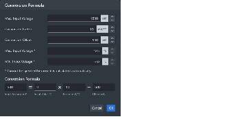
The voltage produced from the specified temperature can be applied to a pin to which the A/D converter is connected. Relational expression between temperature and input voltage:
Voltage (V) input to the connected pin = |
|
|
The fan is made to rotate by the input of a digital signal from the connected pin. The rotational velocity can be controlled by the duty ratio of the PWM signal. |
|
|
The motor is made to rotate by the input of a digital signal from the connected pin. The rotational velocity can be controlled by the duty ratio of the PWM signal. |
|
|
A specified voltage value can be output to the connected pin in response to covering the red light-emitting part by the hand-image icon. |
|
|
When a PWM signal is being input through the connected pin, a sphere revolves around the component to indicate that charging is in progress. |
|
|
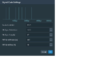
Clicking on the component leads to the output of the signal which has been specified for the connected pin. |
|
|
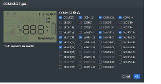
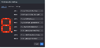
Segment LCD for internal driverNote1 Segments of this LCD are illuminated in response to control signals sent from the LCD driver in the MCU. You can control the correspondence between the MCU's control signals and segments in the property area. |
|
|
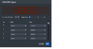
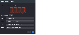
7-segment LEDs for displaying up to eight-digit numbers with dynamic lighting. |
|
|
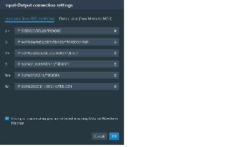
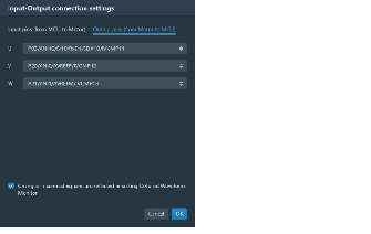
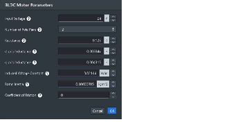
Signals output from the component are used in control by a feedback system. When a three-phase PWM signal is input, the motor rotates. |
|
|
Used for specifying multiple switches for an analog input pin. A maximum of five switches are specifiable. When a switch is pressed, the voltage specified for the given switches is input to the selected analog pin. |
|
|
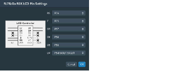
An LCD panel included with the Renesas Starter Kit for RL78/L12Note1, which operates with the on-chip LCD controller of that MCU. |
|
|
An LCD panel for debugging included with the Renesas Starter Kit for RL78/G13, G14.Note3 The panel has a display area with two lines of eight characters. |
|
|
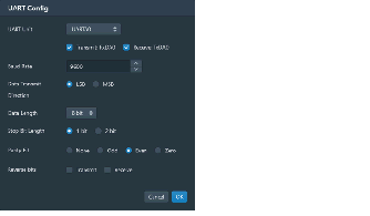
A console used for UART communications with the MCU. The transmitted or received data can be confirmed in the Serial Monitor tab. The serial monitoring area can also be opened by clicking on the icon button at the bottom right corner of the component. |
|
|
Connected to the MCU via the UART to operate as a mock-up component for Wi-Fi communications. When a command is received from the MCU via the UART, a defined response is returned. The transmitted or received data can be confirmed in the Serial Monitor tab. The serial monitoring area can also be opened by clicking on the icon button at the bottom right corner of the component. |
|
|
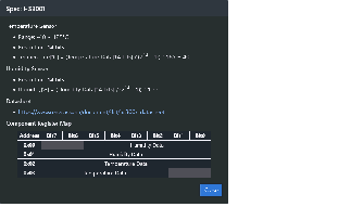
A humidity-temperature sensor for acquiring data on temperature and humidity through I2C communications. Details of the I2C communications can be confirmed on the Serial Monitor tab. The serial monitoring area can also be opened by clicking on the console icon button at the bottom right corner of the component. The register values in the component can be confirmed by clicking on the table icon button next to the center-right side of the component. |
|
|
A character-LCD component for displaying data through I2C communications. The component has a display area with two lines of 16 characters. Details of the I2C communications can be confirmed on the Serial Monitor tab. The serial monitoring area can also be opened by clicking on the console icon button at the bottom right corner of the component. The register values in the component can be confirmed by clicking on the table icon button next to the center-right side of the component. |
|
|
A device for sending and receiving data through I2C communications. The register values in the component can be changed to the desired values. Details of the I2C communications can be confirmed on the Serial Monitor tab. The serial monitoring area can also be opened by clicking on the console icon button at the bottom right corner of the component. The register values in the component can be confirmed by clicking on the table icon button next to the center-right side of the component. |
|
|
An air velocity sensor for acquiring wind-velocity data through I2C communications. Details of the I2C communications can be confirmed on the Serial Monitor tab. The serial monitoring area can also be opened by clicking on the console icon button at the bottom right corner of the component. The register values in the component can be confirmed by clicking on the table icon button next to the center-right side of the component. |
At present, this component is only available for use with devices of the RL78/G13, G13A, and G14 groups. |
Values related to the environment, such as the temperature or humidity in the vicinity of the virtual board, can be specified. Some components operate by acquiring these values.
These buttons are used to add components.
This area is valid while the program is stopped.
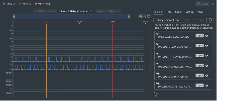
Clicking on the tab shows the detailed waveform monitor.
This monitor displays the waveforms of pins registered beforehand at 500-ns intervals for one millisecond before execution of the program is stopped.
In addition, markers can be used to check the states at particular points and a search function can be used to check whether combinations of states that satisfy certain conditions are present.
For details, refer to the part of the help system that can be displayed from the detailed waveform monitor.
Selecting a tab switches the category in which detailed information is displayed.
The following tabs exist in this panel (for details on what is displayed and how to configure settings on each tab, refer to the corresponding (6) Detailed information display/change area).
This area is used to display or edit the properties of the component.
The properties of the component selected while the program is stopped are displayed.
The following items are displayed in this area.
Displays a list of all pins of the MCU.
Each pin can be used to input a digital or analog value when it is not connected to a component.
The value specified here cannot be changed during program execution.

The serial communication component added to the virtual board allows you to check the contents of data received and send data to the simulator.
An icon button is displayed in the lower right corner of the serial communication component, and clicking the button displays the [Serial Monitor] tab.
UART communication supports hexadecimal notation and ASCII code notation, and data sent from the MCU is prefixed with > is added to the beginning of each line of data sent from the MCU.

For I2C communications, the Serial Monitor tab shows the communication direction (read or write), the slave address of the communication destination, and the communication data. When a single I2C unit is connected to multiple slave addresses, the communication data can be filtered per slave address.

The Virtual Board Panel may use the copyrighted components specified in the file below.


