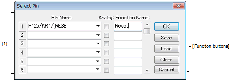
This dialog box is used when selecting pins displayed in the Signal Data Editor window and the Timing Chart window.
The pin information set in this dialog box can be saved as a pin information file (*.pin) by clicking the [Save] button. Moreover, the saved file contents can be restored by clicking the [Load] button.
Figure A.63 | Select Pin Dialog Box |
This section describes the following.
[How to open]
On the Signal Data Editor window/Timing Chart window, any one of the following:
- | Click the  button.
 |
- | Select [Select Pin...] from the [Edit] menu. |
[Description of each area]
(1) | Connection pins setting area |
Up to 256 pins can be selected by using the scrollbar located on the right side of the pin name setting area.
|
Pin Name
|
This area is used to specify the pin name to be connected.
The connection pins can be specified either via direct input or through selection from the drop-down list.
|
|
Analog
|
Select this check box to use the specified pin as an analog pin.
|
|
Function Name
|
This area is used to set a function name for the pin name.
When a character string is input in this area, this character string is displayed as a function name in the pin name part. If nothing is specified, the pin name is displayed.
|
Remark | For the pin names that can be specified, see the user's manual of the microcontroller that is used. |
[Function buttons]
|
|
|
|
OK
|
Validates the settings and closes this dialog box.
The pin name (or display name) is applied in the Pin field of the window from where this dialog box was called up.
|
|
Save
|
Saves the display contents to the pin information file (*.pin).
|
|
Load
|
Loads the pin setting information of the specified file (*.pin).
|
|
Clear
|
Deletes the settings.
|
|
Cancel
|
Cancels the settings and closes this dialog box.
|

 button.