CHAPTER 15 REALTIME OS TASK ANALYZER
The tool for realizing the above is "Realtime OS Task Analyzer". The Realtime OS Task Analyzer analyzes the information outputted by Realtime OS and displays it graphically.
This chapter describes the procedure for using Realtime OS Task Analyzer. See "RI600V4 Analysis" for the functions and operation method of the Realtime OS Task Analyzer.
There is the type of usage shown below in the Realtime OS Task Analyzer. The trace mode is selected in [ Task Analyzer ] tab.
- Taking in trace chart by hardware trace mode
In this mode, the trace information is collected in the trace memory which emulator or simulator has.
In this mode, the trace information is collected in the trace memory which emulator or simulator has.
- Taking in trace chart by software trace mode
In this mode, the trace information is collected in the trace buffer secured on the user memory area. The buffer size is specified in [ Task Analyzer ] tab. Please refer to "15.4 Trace Buffer Size (Taking in Trace Chart by Software Trace Mode)" for the estimate of the size of the trace buffer.
To use this mode, implementation of user-own coding module and setup of the system configuration file are required. For details, refer to "15.3.1 Taking in trace chart by software trace mode".
- Taking in long-statistics by software trace mode
In this mode, the trace information is collected in the RI600V4's variable secured on the user memory area. The size of this variable is roughly 2 K-bytes. For details, refer to "19.20.1 BRI_RAM section".
To use this mode, implementation of user-own coding module and setup of the system configuration file are required. For details, refer to "15.3.2 Taking in long-statistics by software trace mode".
The measurable maximum time and the time precision differ for every trace mode. The standard is shown to Figure 15-1.
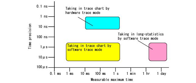
Note 1 In the "Taking in trace chart by hardware trace mode", the measurable maximum time depends on the size of the trace memory which the emulator or simulator has. And the time precision depends on the emulator or simulator specification.
Note 2 In the "Taking in trace chart by softwarre trace mode", the measurable maximum time depends on the size of the trace buffer. And refer to "15.3.1 Taking in trace chart by software trace mode" for the time precision.
Note 3 In the "Taking in long-statistics by software trace mode", refer to "15.3.2 Taking in long-statistics by software trace mode" for the measurable maximum time and the time precision.
When using the Realtime OS Task Analyzer, compared with the case where it is not used,it has the influence shown in Table 15-1 on the target system. Note, the processing time in Table 15-1 is approximate value when the CPU clock is 100MHz.
Reference to the function of each mode , Figure 15-1 and Table 15-1, please decide the trace mode to be used.
The trace mode is selected in [ Task Analyzer ] tab. Then by performing a build, the load module which contains the Realtime OS module that corresponds the trace mode to be selected is generated.
In this mode, the RI600V4 gets time-stamp from user-own coding module. Usually, the hardware timer is used in order to generate time-stamp. The bit width of the counter of the hardware timer has necessity of 16 bits or more. Note, CMT (Compare Match Timer), which is built in RX family MCU as standard, satisfies this requirement.
This section describes the specification of function and variables to be implemented as user-own coding module. Since each function does not follow ABI (Application Binary Interface) of the RX family C/C++ compiler, it needs to be implemented by using assembly language. In this section, function and variable name are described in assembly language level.
Define the unit of the time returned by __RIUSR_trcSW_read_cnt (Function to get time-stamp) as a constant for the 32 bit- unsigned integer. Usually, please set up the time of 1 count of hardware timer counter.
A typical setup in the case of using CMT is shown below.
A typical setup in the case of using CMT is shown below.
2 ) __RIUSR_trcSW_init_tmr (Initialization function)
This function initializes the hardware timer so that specification of __RIUSR_trcSW_read_cnt (Function to get time-stamp) may be realized.
|
|
3 ) __RIUSR_trcSW_read_cnt (Function to get time-stamp)
This function returns the elapsed time from the time of __RIUSR_trcSW_init_tmr (Initialization function) was called. The value returned must be in the range of from 0 and 0x7FFFFFFF, in units of the __RIUSR_trcSW_base_time (Time precision).
|
|
4 ) Interrupt handler (Arbitrary function name)
In this mode, the RI600V4 gets time-stamp from user-own coding module. Usually, the hardware timer is used in order to generate time-stamp. The bit width of the counter of the hardware timer has necessity of 16 bits or more, and must be able to generate an interrupt when the timer clock is counted 65536 times. Note, CMT (Compare Match Timer) standardly built in RX family MCU is satisfying this requirement.
This section describes the specification of function and variables to be implemented as user-own coding module. Since each function does not follow ABI (Application Binary Interface) of the RX family C/C++ compiler, it needs to be implemented by using assembly language. In this section, function and variable name are described in assembly language level.
Define the unit of the time returned by __RIUSR_trcLONG_read_cnt (Function to get time-stamp) as a constant for the 32 bit- unsigned integer.
Usually, please set up the time of 1 count of hardware timer counter.
A typical setup in the case of using CMT is shown below.
Usually, please set up the time of 1 count of hardware timer counter.
A typical setup in the case of using CMT is shown below.
Note 2 Measurable maximum time of interrupt handler execution time = __RIUSR_trcLONG_base_time * 65536
Define the interrupt priority level of the using hardware timer as a constant for the 8 bit- unsigned integer.
The execution time of interrupt handlers with interrupt priority level more than or equal to this interrupt priority level are not measured. The execution time of that interrupt handlers are appropriated for the execution time of the processing program (tasks, another interrupt handlers, or kernel idling) which was executing when that interrupt occurred.
3 ) __RIUSR_trcLONG_init_tmr (Initialization function)
This function initializes the hardware timer so that interruption which interrupt priority level is __RIUSR_trcLONG_timer_lvl (Interrupt priority level) may be generated, when the timer clock is counted 65536 times.
|
|
4 ) __RIUSR_trcLONG_read_cnt (Function to get time-stamp)
This function returns the elapsed time from the previous interruption. The value returned must be in the range of from 0 and 65535 in units of the __RIUSR_trcLONG_base_time (TIme precision).
|
|
5 ) Interrupt handler (Arbitrary function name)
This function is not user-own coding module, is implemented in the RI600V4. The following is a specification of this function.