CHAPTER 2 SYSTEM BUILDING
This chapter describes how to build a system (load module) that uses the functions provided by the RI600V4.
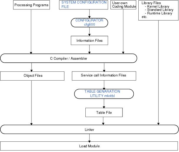
System building consists in the creation of a load module using the files (kernel library, etc.) installed on the user development environment (host machine) from the RI600V4's supply media.
The sample programs are stored in the following folder. The source files are stored in "appli" sub-folder.
In the RI600V4, the processing program is classified into the following four types, in accordance with the types and purposes of the processing that should be implemented.
- Tasks
A task is processing program that is not executed unless it is explicitly manipulated via service calls provided by the RI600V4, unlike other processing programs (interrupt handler, cyclic handler and alarm handler).
A task is processing program that is not executed unless it is explicitly manipulated via service calls provided by the RI600V4, unlike other processing programs (interrupt handler, cyclic handler and alarm handler).
- Cyclic handlers
The cyclic handler is a routine started for every specified cycle time.
The RI600V4 handles the cyclic handler as a "non-task (module independent from tasks)". Therefore, even if a task with the highest priority in the system is being executed, the processing is suspended when a specified activation cycle has come, and the control is passed to the cyclic handler.
- Alarm Handlers
The alarm handler is a routine started only once after the specified time.
The RI600V4 handles the alarm handler as a "non-task (module independent from tasks)". Therefore, even if a task with the highest priority in the system is being executed, the processing is suspended when a specified activation cycle has come, and the control is passed to the cyclic handler.
- Interrupt Handlers
The interrupt handler is a routine started when an interrupt occurs.
The RI600V4 handles the interrupt handler as a "non-task (module independent from tasks)". Therefore, even if a task with the highest priority in the system is being executed, the processing is suspended when an interrupt occurs, and the control is passed to the interrupt handler.
Note For details about the processing programs, refer to "CHAPTER 3 TASK MANAGEMENT FUNCTIONS", "CHAPTER 8 TIME MANAGEMENT FUNCTIONS", "CHAPTER 10 INTERRUPT MANAGEMENT FUNCTIONS".
Code the SYSTEM CONFIGURATION FILE required for creating information files that contain data to be provided for the RI600V4.
Note 1 For details about the system configuration file, refer to "CHAPTER 19 SYSTEM CONFIGURATION FILE".
Note 2 When the Realtime OS Task analyzer is used in "Taking in trace chart by software trace mode" or "Taking in long-statistics by software trace mode", it is necessary to define the interrupt handler implemented in user-own coding module to the system configuration file. For details, refer to "CHAPTER 15 REALTIME OS TASK ANALYZER".
- User-Own Coding Module for Software Trace Mode
When using the software trace mode, user-own coding module to get time-stamp must be implemented.
When using the software trace mode, user-own coding module to get time-stamp must be implemented.
- Boot processing function (PowerON_Reset_PC( ))
The boot processing is defined in the reset vector, and dedicated to initialization processing that is extracted as a user-own coding module to initialize the minimum required hardware for the RI600V4 to perform processing.
And the boot processing plays the role to take the ROM definition file and RAM definition file which are generated by the cfg600.
- Section information file (User-Own Coding Module)
Informations for uninitialized data sections and initialized data sections are defined in the section information file.
Informations for uninitialized data sections and initialized data sections are defined in the section information file.
Note For details about the user-own coding module, refer to "CHAPTER 13 SYSTEM DOWN", "CHAPTER 15 REALTIME OS TASK ANALYZER" and "CHAPTER 16 SYSTEM INITIALIZATION".
Run a build on CubeSuite+ for files created in sections from "2.2 Coding Processing Programs" to "2.4 Coding User-Own Coding Module", and library files provided by the RI600V4 and C compiler package, to create a load module.
Note See "RI Series Start", "CubeSuite+ Start" and the Release Notes of this product for details about creating a new project or loading an existing one.
Note See "CubeSuite+ RX Build" for details about adding or removing build target files for the project and updating the dependencies.
Note Specify "cfg" as the extension of the system configuration file name. If the extension is different, "cfg" is automatically added (for example, if you designate "aaa.c" as a file name, the file is named as "aaa.c.cfg").
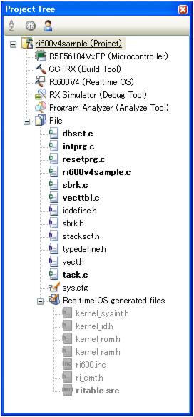
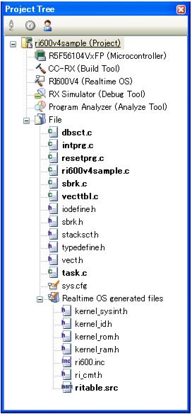
Note 1 If the system configuration file is added to the Project Tree panel, the Realtime OS generated files node is appeared.
The following information files are appeared under the Realtime OS generated files node. However, these files are not generated at this point in time.
The following information files are appeared under the Realtime OS generated files node. However, these files are not generated at this point in time.
Note 2 When replacing the system configuration file, first remove the added system configuration file from the project, then add another one again.
Note 3 Although it is possible to add more than one system configuration files to a project, only the first file added is enabled. Note that if you remove the enabled file from the project, the remaining additional files will not be enabled; you must therefore add them again.
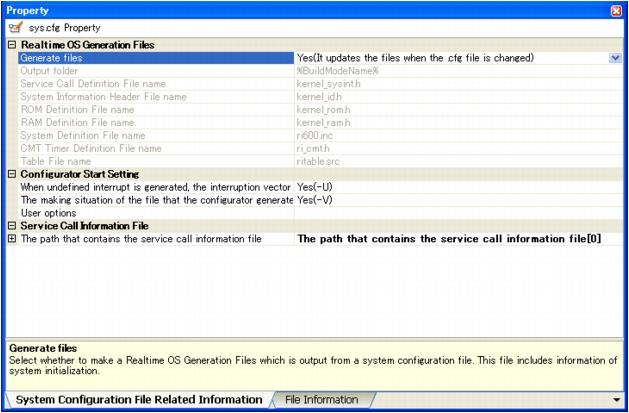
On the [System Configuration File Related Information] tab, set the output of realtime OS generation files, etc.
Set the options for the compiler, assembler, linker, and the like.
Please be sure to refer to "2.6 Build Options".
Please be sure to refer to "2.6 Build Options".
The service call information file (mrc files) are generated to the same folder as object files at compilation of the source files that includes kernel.h file.
The name of service calls used in the source files are outputted in the mrc files. It is necessary to input all files to the table generation utility mkritbl. If there is a leaking in the input file, service call modules that application uses might not be linked. In this case, the system down will occur when the service call is issued.
On the other hand, if the mrc files which are generated in the past and which is invalid in now are input to the mkritbl, the service call modules that are not used in the application may be linked. In this case, there is no problem in the operation of the RI600V4 but the module size uselessly grows.
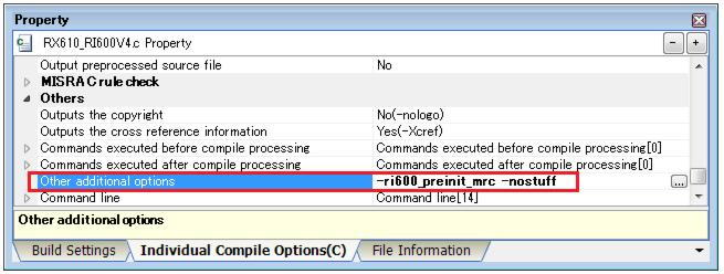
Specify "-ri600_preinit_mrc" compiler option for the source file that includes kernel.h file even if this option is not specified, there is no problem in the operation of the RI600V4 but the service call module that is not used in the application may be linked.
When application libraries are used, the mrc files that is generated at compilation of the library source should be inputted to the mkritbl. If this way is difficult for you, make mrc file where name of using service calls is described (see belows), and input the mrc file to the mkritbl.
It is necessary to set "-nostuff" option for the boot processing file ("resetprg.c" in the sample project) like a mention in "16.2.3 Compiler option for boot processing file". If not, the RI600V4 does not work correctly.
To set "-nostuff" option only for the boot processing file, please set any of the following in the [Individual Compile Options] tab of [Property] panel for the boot processing file. To set "-nostuff" option for all, please set any of the following in the [Compiler Options] tab of [Property] panel for [CC-RX (Build Tool)].
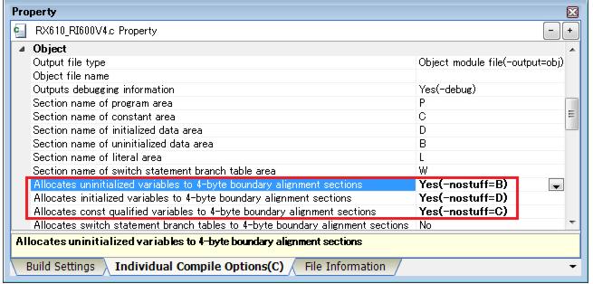
1 ) Set in the [Object] category
Like Figure 2-6, set "Yes" in [Allocates uninitialized variables to 4-byte boundary alignment sections], [Allocates initialized variables to 4-byte boundary alignment sections] and [Allocates const qualified variables to 4-byte boundary alignment sections].
Like Figure 2-6, set "Yes" in [Allocates uninitialized variables to 4-byte boundary alignment sections], [Allocates initialized variables to 4-byte boundary alignment sections] and [Allocates const qualified variables to 4-byte boundary alignment sections].
The kernel libraries are stored in the folders described in Table 2-1. Note, CubeSuite+ links the appropriate kernel library automatically, you need not consider the kernel libraries.
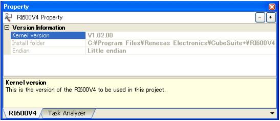
Note 1 <ri_root> indicates the installation folder of RI600V4.
The default folder is "C:\Program Files\Renesas Electronics\CubeSuite+\RI600V4".
The default folder is "C:\Program Files\Renesas Electronics\CubeSuite+\RI600V4".
Note 2 The kernel described in item-2 of Table 2-1 is linked when compiler V2.01.00 or later is used. In the case of others, the kernel library described in item-1 of Table 2-1 is linked.
Arrangement section is defined by using "-start" linker option. In CubeSuite+, it is set in [Section] category of [Link Options] tab in [Property] panel for [CC-RX (Build Tool)].
Table 2-2 RI600V4 sections
This section is generated only when "Taking in trace chart by software trace mode" and "Kernel buffer" are selected in [ Task Analyzer ] tab. The size is specified in [ Task Analyzer ] tab.
|
||||
The configurator cfg600 generates fixed vector table/exception vector table as FIX_INTERRUPT_VECTOR section according to the contents of definitions of "interrupt_fvector[]" in the system configuration file.
- At the time of RXv1 architecture use
In the RXv1 architecture, fixed vector table is being fixed to address 0xFFFFFF80. It is necessary to arrange the FIX_INTERRUPT_VECTOR section at address 0xFFFFFF80.
When the FIX_INTERRUPT_VECTOR section is not arranged to address 0xFFFFFF80, all "interrupt_fvector[]" in the system configuration file are ignored. And the system-down function when an exception (except Reset) assigned to fixed vector table is occurred does not operate normally. Please generate fixed vector table to address 0xFFFFFF80 by the user side.
- At the time of RXv2 architecture use
In the RXv2 architecture, the name of fixed vector table is changed into exception vector table, and can set up the start address by EXTB register. The initial value of EXTB register at the time of reset is 0xFFFFFF80, it is same as fixed interrupt vector table in RXv1 architecture.
Usually, please arrange the FIX_INTERRUPT_VECTOR section to address 0xFFFFFF80.
When the FIX_INTERRUPT_VECTOR section is not arranged to address 0xFFFFFF80, "interrupt_fvector[31]" (reset vector) in the system configuration file is ignored. Please generate the reset vector (address 0xFFFFFFFC) by the user side. And initialize EXTB register to the start address of FIX_INTERRUPT_VECTOR section in Boot processing function (PowerON_Reset_PC( )).
About sections described in DTBL of the Section information file (User-Own Coding Module), it is necessary to perform setting to map sections placed on ROM to sections placed on RAM by using "-rom" linker option. Set [Link Options] tab of [Property] panel for [CC-RX (Build Tool)] like Figure 2-8.
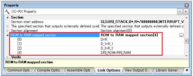
Note In sample projects provided by RI600V4, it is already set up that the "DRI_ROM" section of RI600V4 is mapped to "RRI_RAM" section.
According to a setup of [Task Analyzer] tab, the build-options shown in Table 2-3 are set up automatically. Note, this automatic setting function is not being interlocked with corresponding property panel of a function. For this reason, don't change the contents set up automatically in corresponding property panel of a function.
Table 2-3 The options set up automatically for Realtime OS Task Analyzer