Debugging of CAN bus reception is a feature for facilitating debugging of the reception procedure of a channel by continuously transmitting CAN bus frames to a desired channel by using the inter-channel communications facility of the RS-CAN.
This feature can be used when the target device has RS-CAN units which consists two or more channels. |
Open the Solution List panel and click the [GO] button for Debugging CAN Bus Reception Procedures to open the Debugging CAN Bus Reception Procedures panel [Full-spec emulator][E1][E20].
Operation of the CAN bus reception procedure for an individual microcontroller can be verified using this feature.
The preparations that have to be made before starting debugging of CAN bus reception are explained below.
Select the clock source and specify whether to use the timestamp, DLC checking function, and DLC replacement functions as the settings of the entire RS-CAN (see "RS-CAN Module Setting dialog box [Full-spec emulator][E1][E20]").
The meaning of each setting is as follows:
As shown in the figure below, the RS-CAN has three types of clock input: clk_xincan, clkc, and pclk.
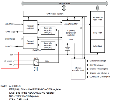
For clk_xincan and clkc among the clock inputs, the clock that is to be input to the baud rate prescaler of each channel needs to be selected with switch [1] in the figure.
The clock source for the microcontroller to which each clock input is connected differs depending on the device. See the hardware manual of the device for details.
This function stores the timestamp of the frame reception time in a receive buffer or receive FIFO.
At debugging of CAN bus reception, the input clock of the timer for timestamp is a clock obtained by dividing the frequency of pclk by 2.
Set whether to apply filtering by the Data Length Code (DLC) when receiving a frame in the RS-CAN.
Since this setting is effective for not each channel but the entire RS-CAN module, this has been made a setting of the entire RS-CAN.
When the DLC checking function is used, a frame larger than or equal to the data size set in the [Receive rule settings] area of the Receive Channel Setting dialog box [Full-spec emulator][E1][E20] can pass the filter.
Make this setting in accordance with your system.
When the frame passes the filter of the DLC checking function, the DLC code is replaced with a value of the data size defined by receive rules.
This function is enabled only when the DLC checking function is used.
When the data size of the frame that was received using the DLC replacement function is larger than or equal to the data size defined by receive rules, DLC is replaced with 0x0. |
Set the channel number, reception speed, number of receive buffers to be used, receive FIFO number to be used, and receive rules of the receive channel that is the target of debugging of CAN bus reception in the Receive Channel Setting dialog box [Full-spec emulator][E1][E20].
Specify the number of the receive channel for which debugging of CAN bus reception is to be performed.
Specify the channel to call the reception procedure you wish to debug.
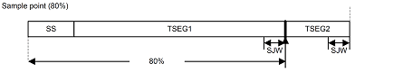
The reception speed is determined by setting the frequency division ratio of the baud rate prescaler, the time unit of a propagation time segment, the time unit of a phase buffer segment, and the time unit of the resynchronization jump width.
The baud rate prescaler sets the frequency division ratio of the clock selected in "<1> Select the clock source".
The cycle of this divided clock is one time unit (Tq).
The relationship between the sample time for the RS-CAN to acquire one bit of data, the propagation time segment, the phase buffer segment, and the resynchronization jump width is shown below. The final reception speed is determined by this relationship.
In the RS-CAN, the receive buffers for each channel is a continuous area. When the number of receive buffers is specified, it means that the receive buffers with the number of 0 to (Receive buffer count - 1) are specified.
A receive buffer holds a single frame of data per one number.
FIFOs can be used to store received frames in the RS-CAN. 128 frames of data can be stored in a single FIFO.
These are filter settings for sorting received frames into receive buffers or FIFOs.
Filtering is based on the ID, frame type, and data size.
By specifying a label for each receive rule, you can identify the receive rule that was applied.
Set the channel number used to transmit frames for debugging and the interval time for continuously transmitting frames in the Transmit Channel Setting dialog box [Full-spec emulator][E1][E20].
One channel is occupied for transmitting frames because the inter-channel communication facility of the RS-CAN module is used for debugging of CAN bus reception.
Specify the number of an unused channel or a channel that is not a target of debugging.
The base clock of the interval time for continuous transmission is a clock obtained by dividing the frequency of pclk by 2, as shown in the figure in "<1> Select the clock source".
Specify the division ratio for the base frequency, how many clock cycles of the divided clock are to be used, or whether the interval time should be multiplied by 10.
Set the frame to be transmitted in the Transmit Frame Setting dialog box [Full-spec emulator][E1][E20].
The CAN bus frames that can be specified in debugging of CAN bus reception are only data frames and remote frames.
Set the type, ID, data size, and data of the frame you wish to transmit to the channel that is a target of debugging.
The set frame will be transmitted at the interval time set in "<2> Interval time of continuous transmission".
Specify the timing to apply the settings that have been set so far.
For the timing to apply the settings, specify immediately after debugging of CAN bus reception is executed or upon execution of the instruction at the specified address.
Since debugging of CAN bus reception changes the settings of the RS-CAN module, the settings should be applied after the RS-CAN module setting process in the user code has finished.
Debugging of CAN bus reception can be started by setting a breakpoint at the address of a function in the reception procedure that is to be debugged and then clicking  from the toolbar on the panel.
Normal debugging can be performed after the program stops at the set breakpoint.