CHAPTER 10 INTERRUPT MANAGEMENT FUNCTIONS
The RI850V4 provides as interrupt management functions related to the interrupt handlers activated when an EI level maskable interrupt is occurred.
To support various execution environments, the RI850V4 extracts from the interrupt management functions the hardware-dependent processing (Interrupt entry processing) that is required to execute processing, as a user-own coding module. This enhances portability for various execution environments and facilitates customization as well.
Interrupt entry processing is a routine dedicated to entry processing that is extracted as a user-own coding module to assign processing for branching to the relevant processing (such as interrupt preprocessing), to the handler address to which the CPU forcibly passes control when an interrupt occurs.
The interrupt entry processing for the EI level maskable interrupts defined in the Interrupt handler information in the system configuration file is included in the entry file created by executing the configurator for the system configuration file. Therefore, coding of interrupt entry processing is necessary for other interrupts (such as a reset) that are not EI level maskable interrupts.
- Basic form of interrupt entry processing
When coding an interrupt entry processing, the code should match the branch method selected in the Property panel -> [System Configuration File Related Information] tabbed page -> [Entry File] category -> [Generate method].
The following shows the basic form of interrupt entry processing in assembly language, related to other interrupts (such as EI level maskable interrupts not defined in the Interrupt handler information, reset, or FE level maskable interrupts) that are not EI level maskable interrupts defined in the Interrupt handler information in the system configuration file.
For interrupt types other than the EI level maskable interrupt, interrupt entry processing should always be coded in the direct vector method.
.extern _inthdr -- External label declaration .org base_adress + offset -- Setting of branch destination address jr32 _inthdr -- Branch to interrupt processing |
Note Set base_address to the same value as that specified in the Property panel -> [System Configuration File Related Information] tabbed page _ [Entry File] category -> [Specify an exception handler vector address].
Set offset to the offset value corresponding to the priority of the target interrupt.
Set offset to the offset value corresponding to the priority of the target interrupt.
.extern _inthdr -- External label declaration .org base_adress + offset -- Setting of branch destination address dw !_inthdr -- Branch to interrupt processing |
Note Set base_address to the same value as that specified in the Property panel -> [System Configuration File Related Information] tabbed page _ [Entry File] category -> [Base address of the interrupt handler address table].
Set offset to the offset value corresponding to the source of the target interrupt.
Set offset to the offset value corresponding to the source of the target interrupt.
- Internal processing of interrupt entry processing
Interrupt entry processing is a routine dedicated to entry processing that is called without RI850V4 intervention when an interrupt occurs. Therefore, note the following points when coding interrupt
Interrupt entry processing is a routine dedicated to entry processing that is called without RI850V4 intervention when an interrupt occurs. Therefore, note the following points when coding interrupt
- Coding method
Code it in assembly language according to the calling convention in the compiler used.
Code it in assembly language according to the calling convention in the compiler used.
- Stack switching
There is no stack that requires switching before executing interrupt entry processing.
Therefore, coding regarding stack switching is not required in interrupt entry processing.
There is no stack that requires switching before executing interrupt entry processing.
Therefore, coding regarding stack switching is not required in interrupt entry processing.
- Service call issue
To achieve faster response for processing (such as an Interrupt Handlers) corresponding to an interrupt that has occurred, the issue of service calls is prohibited during interrupt entry processing.
To achieve faster response for processing (such as an Interrupt Handlers) corresponding to an interrupt that has occurred, the issue of service calls is prohibited during interrupt entry processing.
The interrupt handler is a routine dedicated to interrupt servicing that is activated when an EI level maskable interrupt occurs.
The RI850V4 handles the interrupt handler as a non-task (module independent from tasks). Therefore, even if a task with the highest priority in the system is being executed, the processing is suspended when an interrupt occurs, and the control is passed to the interrupt handler.
The RI850V4 manages the states in which each interrupt handler may enter and interrupt handlers themselves, by using management objects (interrupt handler control blocks) corresponding to interrupt handlers one-to-one.
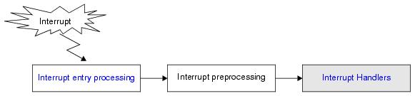
The following shows a processing flow from when an interrupt occurs until the control is passed to the interrupt handler.
#include <kernel.h> /*Standard header file definition*/ #include <kernel_id.h> /*System information header file definition*/ void inthdr (void) { ......... return; /*Terminate interrupt handler*/ } |
The RI850V4 executes "original pre-interrupt processing" when passing control from the processing program where an EI level maskable interrupt occurred to the interrupt handler, as well as "original post-interrupt processing" when restoring control from the interrupt handler to the processing program where the EI level maskable interrupt occurred. Therefore, note the following points when coding interrupt handlers.
- Coding method
Code interrupt handlers using C or assembly language.
When coding in C, they can be coded in the same manner as ordinary functions coded.
When coding in assembly language, code them according to the calling rules prescribed in the compiler used.
Code interrupt handlers using C or assembly language.
When coding in C, they can be coded in the same manner as ordinary functions coded.
When coding in assembly language, code them according to the calling rules prescribed in the compiler used.
- Stack switching
The RI850V4 switches to the system stack specified in Basic information when passing control to an interrupt handler, and switches to the relevant stack when returning control to the processing program for which a base clock timer interrupt occurred. Coding regarding stack switching is therefore not required in interrupt handler processing.
The RI850V4 switches to the system stack specified in Basic information when passing control to an interrupt handler, and switches to the relevant stack when returning control to the processing program for which a base clock timer interrupt occurred. Coding regarding stack switching is therefore not required in interrupt handler processing.
- Service call issue
The RI850V4 handles the interrupt handler as a "non-task".
Service calls that can be issued in interrupt handlers are limited to the service calls that can be issued from non-tasks.
The RI850V4 handles the interrupt handler as a "non-task".
Service calls that can be issued in interrupt handlers are limited to the service calls that can be issued from non-tasks.
Note 1 If a service call (isig_sem, iset_flg, etc.) accompanying dispatch processing (task scheduling processing) is issued in order to quickly complete the processing in the interrupt handler during the interval until the processing in the interrupt handler ends, the RI850V4 executes only processing such as queue manipulation, counter manipulation, etc., and the actual dispatch processing is delayed until a return instruction is issued by the interrupt handler, upon which the actual dispatch processing is performed in batch.
Note 2 For details on the valid issue range of each service call, refer to Table 16-1 to Table 16-12.
- Acceptance of EI level maskable interrupts
When passing control to an interrupt handler, the RI850V4 disables acceptance of EI level maskable interrupts by manipulating the PMn bits (set to enabled) in the priority mask register (PMR) and the ID bit (set to disabled) in the program status word (PSW).
When passing control to an interrupt handler, the RI850V4 disables acceptance of EI level maskable interrupts by manipulating the PMn bits (set to enabled) in the priority mask register (PMR) and the ID bit (set to disabled) in the program status word (PSW).
The RI850V4 supports the static registration of interrupt handlers only. They cannot be registered dynamically by issuing a service call from the processing program.
Static interrupt handler registration means defining of interrupt handlers using static API "DEF_INH" in the system configuration file.
The RI850V4 realizes the TIME MANAGEMENT FUNCTIONS by using base clock timer interrupts that occur at constant intervals.
If a base clock timer interrupt occurs, The RI850V4's time management interrupt handler is activated and executes time-related processing (system time update, delayed wakeup/timeout of task, cyclic handler activation, etc.).
Note If acknowledgment of the relevant base clock timer interrupt is disabled by issuing loc_cpu, iloc_cpu or dis_int, the TIME MANAGEMENT FUNCTIONS may no longer operate normally.
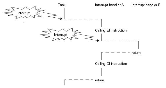
Execution of interrupt handler is started in the interrupt disabled state (the ID flag of the program status word PSW is set to 1). To generate multiple interrupts, processing to cancel the interrupt disabled state (such as issuing of EI instruction) must therefore be coded in the interrupt handler explicitly.