|
Parts Level Gauge Properties dialog box
|
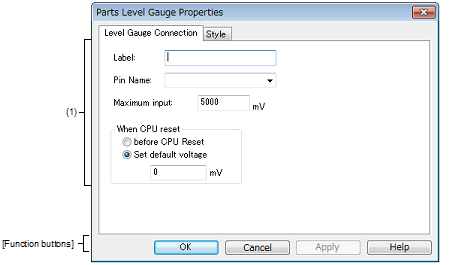
This property dialog box is used to set or change the pin connection information of level gauge, which are one of the connection parts in the I/O Panel window.
Input to the simulator can be done from pin-connected level gauge in the Simulation mode.
Note that the connection pin must be an analog input pin.
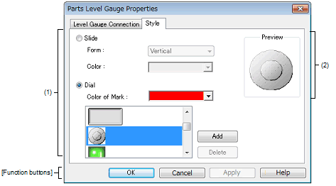
There are two types of level gauge display styles, slide and dial. These styles can be changed on the [[Style] tab].
Figure A.70 | Parts Level Gauge Properties Dialog Box: [Level Gauge Connection] Tab |
Figure A.71 | Parts Level Gauge Properties Dialog Box: [Style] Tab |
This section describes the following.
[How to open]
On the I/O Panel window, any one of the following:
- | Double-click a part object "Level Gauge". |
- | Select [Properties...] form the context menu on a part object "Level Gauge". |
- | Select a part object "Level Gauge", and then select [Properties...] form the [View] menu. |
[Level Gauge Connection] tab]
(1) | Pin connection information setting area |
|
Label
|
This area is used to specify the part name. The part name input here is also displayed in the Parts List dialog box as the label.
|
|
Pin Name
|
This area is used to specify the pin name to be connected. The connection pins can be specified either via direct input or through selection from the drop-down list.
|
|
Maximum input
|
This area is used to set the maximum level gauge input value (default: 5000mV).
The settable range is from 0 to 65535.
The operation range of the level gauge displayed in the I/O Panel window is determined by this specified value.
|
|
When CPU reset
|
Specify the level gauge operation after CPU reset.
|
|
before CPU Reset
|
Maintains the level gauge status of immediately before CPU reset, after CPU reset.
|
|
Set default voltage
|
The level gauge is set to the specified value after CPU reset (default).
Specify the value in mV units.
Input a value from 0 to "Maximum input:". (default: 0 mV)
|
Remark | For the pin names that can be specified, see the user's manual of the microcontroller that is used. |
[[Style] tab]
(1) | Style information setting area |
|
Slide
|
Select this option button to display the level gauge with the side-type.
|
|
Form
|
Select the slide direction (vertical or horizontal) from the drop-down list.
|
|
Color
|
This area is used to specify or change the slide color.
You can change the color by clicking the pull-down button.
|
|
Dial
|
Select this option button to display the level gauge with the dial-type (default).
|
|
Color of Mark
|
This area is used to specify or change the color of the mark indicating the operating point.
You can change the color by clicking the pull-down button.
|
|
Selection list
|
Select a bitmap to be used from the selection list.
The selectable bitmaps appear in the selection list.
|
|
[Add] button
|
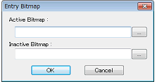
Opens the Entry Bitmap dialog box below to add a new bitmap to the selection list.
The bitmap file to be added can be specified either through file selection using the [...] button, or through direct input.
|
|
[Delete] button
|
Deletes the currently selected bitmap from the selection list.
Note that only the bitmap that have been added by user can be deleted.
|
This area displays the style of the level gauge currently being specified.
[Function buttons]
|
|
|
|
OK
|
Validates the settings and closes this dialog box.
|
|
Cancel
|
Cancels the settings and closes this dialog box.
|
|
Apply
|
Cannot be selected.
|
|
Help
|
Displays the help for this dialog box.
|
[Operation]
In the Simulation mode, analog input from the level gauge is performed through manipulation of the displayed slider or dial.
The value specified in [Maximum input] is the maximum value that can be input.
Input is enabled by selecting the [Figure] menu >> [Simulation Mode].
Figure A.72 | Connected Parts Display Example (Level Gauge) |
|
Dial-type level gauge
|
The displayed analog value changes as the operating point (red circle) on the dial is moved by dragging it with the mouse. When this analog value has become the value that is to be input, release the operating point. As a result, the displayed analog value is input. The operating point can also be moved by clicking the desired location on the dial.
|
|
Slide-type level gauge
|
The displayed analog value changes as the slider button is moved by dragging it with the mouse. When this analog value has become the value that is to be input, release the button. As a result, the displayed analog value is input. The button can also be moved by clicking the desired location on the slider.
|
Caution | If you drag and drop the dial's operation point (red circle) or the slider's knob away from the level gauge, then the voltage displayed in the level gauge will change, but the voltage actually output by the level gauge will not change. Make sure to always drag and drop over the level gauge. |


