|
Memory Mapping dialog box
|
This dialog box sets memory mappings separately for each memory type.
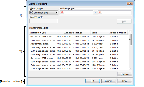
Figure A.43 | Memory Mapping Dialog Box [E1] [E20] [EZ Emulator] |
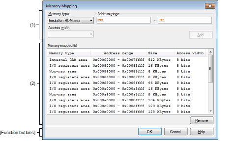
Figure A.44 | Memory Mapping Dialog Box [Simulator] |
This section describes the following.
[How to open]
Caution 1. | [Simulator]
This dialog box cannot be opened during program execution. |
Caution 2. | [E1] [E20] [EZ Emulator]
This dialog box cannot be opened after a debug tool is connected. |
[Description of each area]
(1) | Additional memory mapping specification area |
Specify information on a new memory mapping to be added.
Select the memory type of a memory mapping to be added from the drop-down list shown below. (The items selected by default depend on the debug tool.)
|
Emulation ROM area
[Simulator]
|
Adds an emulation ROM area.
Uses simulator alternative ROM.
|
|
Emulation RAM area
[Simulator]
|
Adds an emulation RAM area.
Uses simulator alternative RAM.
|
|
I/O protection area
[E1] [E20] [EZ Emulator]
|
Adds an I/O protection area.
Specify an address range in the external area that is not to be read by the debugger.
|
Caution 1. | [Simulator]
Memory mapping can be added in the unit of 16 bytes. If you set it outside the 16-byte boundary, compensation will be made to meet the 16-byte boundary area which includes the area set after [OK] is clicked. |
Caution 2. | [Simulator]
Both read and write accesses to the memory mapping that has been added take one cycle each. |
Caution 3. | [E1] [E20] [EZ Emulator]
When the [OK] button is clicked on, each I/O protection area that has been added is adjusted to the access width of the external area that includes that I/O protection area. |
Specify the beginning and the end addresses of a memory mapping to be added. Enter a hexadecimal value directly in the respective text boxes.
When an emulator is in use, I/O protection areas can be allocated to space that overlaps with external areas. Each I/O protection area cannot be allocated to two or more external areas.
When the simulator is in use, you cannot add memory mappings to the areas that overlap the following memory types. (A message will appear if you click [Add] button in these areas.)
Access width cannot be specified.
|
|
|
|
Add
|
Adds the content specified in this area to memory mappings.
The added memory mapping is displayed in the [Memory mapped list] area.
Note that the changed content is not set until the [OK] button is pressed.
|
(2) | [Memory mapped list] area |
Displays memory mappings added in the Additional memory mapping specification area and information on the microcontroller's internal memory mappings. This area cannot be edited.
|
Memory type
|
Following memory types are displayed:
- | External area (CS7/CS6/.../CS0) [E1] [E20] [EZ Emulator] |
- | Other memory area [E1] [E20] [EZ Emulator] |
- | Reserved area [E1] [E20] [EZ Emulator] |
- | I/O protection area [E1] [E20] [EZ Emulator] |
- | Emulation ROM area [Simulator] |
- | Emulation RAM area [Simulator] |
- | Non-map area [Simulator] |
|
|
Address range
|
Displays an address range <Start address> - <End address>.
The addresses are always expressed in hexadecimal, with "0x" added.
|
|
Size
|
Displays a size in decimal (in byte or Kbyte units).
|
|
Access width
|
Displays an access width (in bit units)Note.
|
Note | Since access width is not supported in the simulator, a fixed value (8 bit) will be displayed. The simulation execution time will not be affected by the access width value. |
|
|
|
|
Remove
|
Deletes a memory mapping selected in this area.
When an emulator is in use, only I/O protection areas can be deleted.
When the simulator is in use, the memory area that can be deleted is either an Emulation ROM area or an Emulation RAM area. (The microcontroller's internal memory mappings cannot be deleted.)
|
[Function buttons]
|
|
|
|
OK
|
Sets a currently set memory mapping in the debug tool and then closes this dialog box.
|
|
Cancel
|
Nullifies changes made to memory mappings and then closes this dialog box.
|
|
Help
|
Displays help for this dialog box.
|

