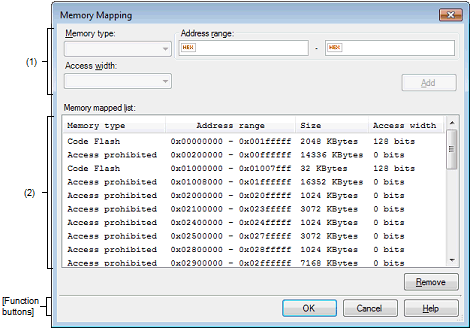
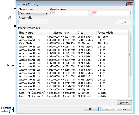
This dialog box is used to set the memory mapping for each type of memory.
When the selected microcontroller supports multi-core, this property displays the memory mapping status regarding a core (PE) by switching selection between the target cores (see "2.7 Select a Core (PE)"). |


This section describes the following.
On the [Debug Tool Settings] tab of the Property panel, click the [...] button displayed by selecting one of the values of the [Memory mappings] property in the [Memory] category. |
Specify the information for a memory mapping newly added.
This area is always invalid except for in the simulator.
Select the memory type for the memory mapping to be added from the following drop-down list (The item selected by default differs depending on the debug tool to use).
|
This area is for testing and it can be accessed from the user program. It can be allocated to only space that overlaps with [Access prohibited]. |
Mapping attributes and their sizes that can be set are as follows:
Specify the start address and end address for the memory mapping to be added. Directly input a hexadecimal number into the text box for each.
In the case of the following settings, however, new memory mappings cannot be added (Clicking the [Add] button in this area causes an error message to be displayed).
If the specified address range duplicates the memory area other than [Access prohibited] when [Temporary] is selected as the memory type |
|
Adds the content specified in this area to memory mapping. The added memory mapping is displayed in the [Memory mapped list] area. The changes will not take effect until the [OK] button is clicked. |
Information about the memory mapping added in the Added memory mapping specification area and the microcontroller's internal memory mapping is displayed.
|
Displays the address range as <Start address> - <End address>. |
|
|
Displays size as a decimal number (unit: bytes/KbytesNote 2). |
|

 : Valid