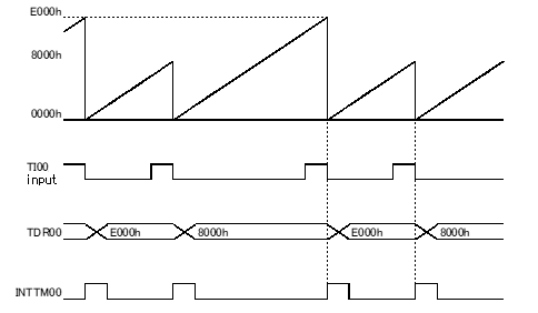
Usage example (Input pulse interval measuremen)
Measure the interval of the falling edges input to TImn pin.
[Waveform example]

[GUI setting example]
|
Timer |
Used | |||
|
TAU0 |
Used | |||
|
Channel0 |
||||
|
channel 0 |
Input pulse interval measurement | |||
|
Input source setting |
TI00 | |||
|
TI00 interval range |
0.125 (μs) < TI00 < 8.192 (ms) | |||
|
Enable using noise filter of TI00 pin input signal |
Unused | |||
|
Generates INTTM00when counting is started. |
Unused | |||
|
Input edge setting |
Falling edge | |||
|
End of timer channel0 capture, generate an interrupt (INTTM00) |
Used | |||
|
Priority |
Low | |||
Remark The period of count clock is 1/2 of the minimum value in the eage selected TI00 interval range. At this GUI setting example, the period of count clock is 0.0625usec.
[API setting example]
r_main.c
void main(void)
{
R_MAIN_UserInit();
/* Start user code. Do not edit comment generated here */
/* Start TAU0 channel 0 counter */
R_TAU0_Channel0_Start();
while (1U)
{
;
}
/* End user code. Do not edit comment generated here */
}
r_cg_timer_user.c
/* Start user code for global. Do not edit comment generated here */
volatile uint32_t g_width = 0UL;
/* End user code. Do not edit comment generated here */
static void __near r_tau0_channel0_interrupt(void)
{
if ((TSR00 & _0001_TAU_OVERFLOW_OCCURS) == 1U) /* overflow occurs */
{
g_tau0_ch0_width = (uint32_t)(TDR00 + 1U) + 0x10000U;
}
else
{
g_tau0_ch0_width = (uint32_t)(TDR00 + 1U);
}
/* Start user code. Do not edit comment generated here */
/* Get TAU0 channel 0 input pulse width. Pulse width(usec) = (Period of count clock(usec) * g_width) */
R_TAU0_Channel0_Get_PulseWidth((uint32_t *)&g_width);
/* End user code. Do not edit comment generated here */
}