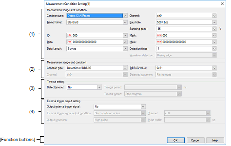
This dialog box is used to set conditions for measurement in the Measuring CAN Bus Reception Processing Times panel [E2].
You can make settings for the measurement condition with the number you have selected before opening this dialog box.

This section describes the following.
On the Measuring CAN Bus Reception Processing Times panel [E2], click [Set Condition 1...] or [Set Condition 2...] from the [Set Condition] button on the toolbar. |
This area allows you to select conditions that define the beginning of the range over which measurement of CAN bus reception processing times will proceed.
Select "Detect CAN Frame" or "Detect External Trigger Input Signal" as the type of the condition.
Select ch0 or ch1 as the channel number to be detected, that is, the number of the CAN channel or external trigger input channel depending on whether "Detect CAN Frame" or "Detect External Trigger Input Signal" has been selected for [Condition type].
If you have selected "Detect CAN Frame" for [Condition type], select "Standard" or "Extended" as the format of CAN frames to be detected.
If you have selected "Detect CAN Frame" for [Condition type], select one of the following values as the bit rate for use in the detection of CAN communications.
1M bps (default), 500K bps, 250K bps, 125K bps
If you have selected "Detect CAN Frame" for [Condition type], specify the relative position as a percentage within one bit period for the sampling of each bit of data in CAN frames to be detected. Decimal values from 1 to 100 can be specified.
If you have selected "Detect CAN Frame" for [Condition type], specify ID in CAN frames to be detected and the mask value to be used as hexadecimal values.
The range of values that can be specified varies depending on selection of [Frame format] as shown below.
When 0 is selected for a mask bit, the bit is treated as being masked.
If [Mask] is blank, all current ID bits are treated as not being masked.
If you have selected "Detect CAN Frame" for [Condition type], specify data in CAN frames to be detected and the mask value to be used as hexadecimal values in the range from 0 to FFFFFFFFFFFFFFFF.
The values specified in the sequence are assumed to be in data fields 0, 1, 2, …, in that order, within the CAN frames. When the value of the last digit takes up less than one byte, the lower-order bits are padded with 0.
When the input value is 0011223, it is assumed that 0x00 is to be found in data field 0, 0x11 in data field 1, 0x22 in data field 2, and 0x30 in data field 3. |
When 0 is selected for a mask bit, the bit is treated as being masked.
If [Mask] is blank, all current ID bits are treated as not being masked.
If you have selected "Detect CAN Frame" for [Condition type], select the data size in bytes for CAN frames to be detected as a value from 0 to 8.
If you have selected "Detect CAN Frame" for [Condition type], time measurement starts when CAN frames have been detected the number of times specified in this field.
If you have selected "Detect External Trigger Input Signal" for [Condition type], select the type of the external trigger input waveform to be detected from the following drop-down list.
This area allows you to select conditions that define the end of the range over which measurement of CAN bus reception processing times will proceed.
Select "Detection of DBTAG" or "Detection of external input trigger signal" as the type of the condition.
If you have selected "Detection of DBTAG" for [Condition type], select the value of DBTAG to be detected.
The facility for measuring CAN bus reception processing times supports the following ten values.
0x21, 0x29, 0x31, 0x39, 0x41, 0x49, 0x51, 0x59, 0x61, 0x69
If you have selected "Detection of external input trigger signal" for [Condition type], select ch0 or ch1 as the channel number to be detected.
If you have selected "Detection of external input trigger signal" for [Condition type], select the type of the external trigger input waveform to be detected from the following drop-down list.
This area allows you to make timeout settings for the measurement of CAN bus reception processing times.
Select whether to detect timeout.
Enter a decimal value from 0 to 2,345,624,805,922,133 (in nanoseconds) as the timeout value.
Select the action on timeout detection from the following drop-down list.
|
Detection of timeout is only used as a condition for external trigger output. |
|
|
Tracing within the MCU stops but execution of the program continues. |
|
"Stop internal tracing" is not selectable as the action on timeout detection when "Detection of DBTAG" is selected as the type of measurement-end condition. |
This area allows you to make settings for the output of external trigger signals in cases where measuring CAN bus reception processing times needs to work with an external device.
Select whether to output an external trigger signal.
Select the timing for the output of an external trigger signal from the following drop-down list.
"Start condition is true" is not selectable when "Detect External Trigger Input Signal" is selected as the type of measurement-start condition. |
Select ch0 or ch1 as the channel from which an external trigger signal will be output.
The waveform of the pulse signal to be output as the external trigger is displayed.
Specify the width of the pulse signal to be output as the external trigger as a decimal value from 1 to 65535 (in microseconds).
|
Clicking on this button applies the conditions set in this dialog box as measurement conditions in the Measuring CAN Bus Reception Processing Times panel [E2]. |
|