16. Quick Start for Renesas RH850 FSP
16.1. Supported Environments
Operating System |
Windows: Windows 10 / Windows 11 |
VS Code version |
1.102.0 (minimum) |
VS Code can be downloaded and installed from this page https://code.visualstudio.com/.
16.2. Installation
Please choose your operating system for operating system dependent installation steps.
For the Renesas RH850 Family, Renesas Platform provides a straightforward installation wizard to install the CMake, Ninja, Python and the Support Files for RH850 Family. To set up your environment:
Open VS Code.
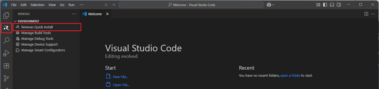
Navigate to the “Renesas” tab in VS Code. Then, click “Renesas Quick Install” in the “Environment” view.
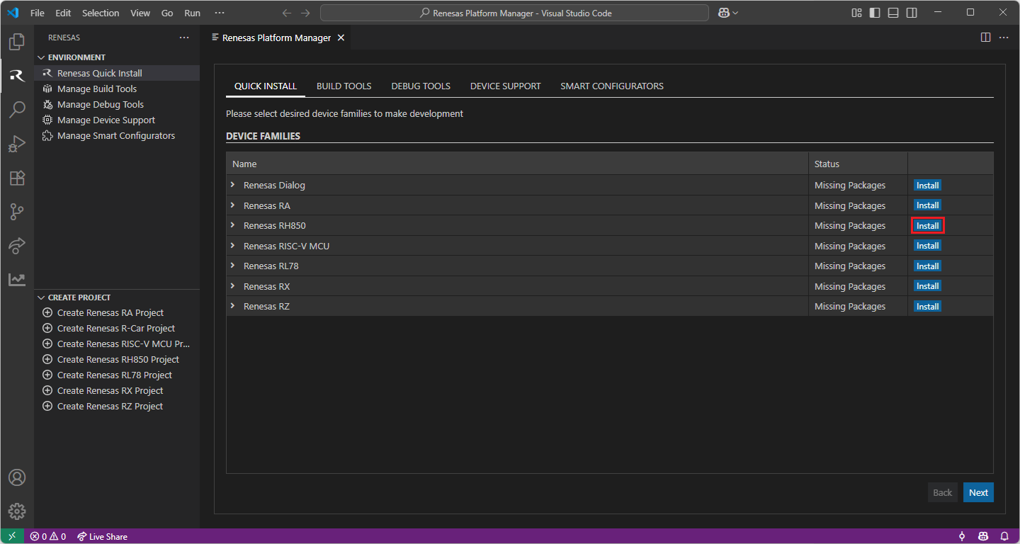
Click the “Install” button for the “Renesas RH850” device family. The Renesas Platform will now check the dependencies required by the Renesas RH850 Device Family. The Renesas Platform extension will check the local environment and CMake, Ninja, Python and the Support Files for RH850 Family, then create an installation plan for them if necessary.
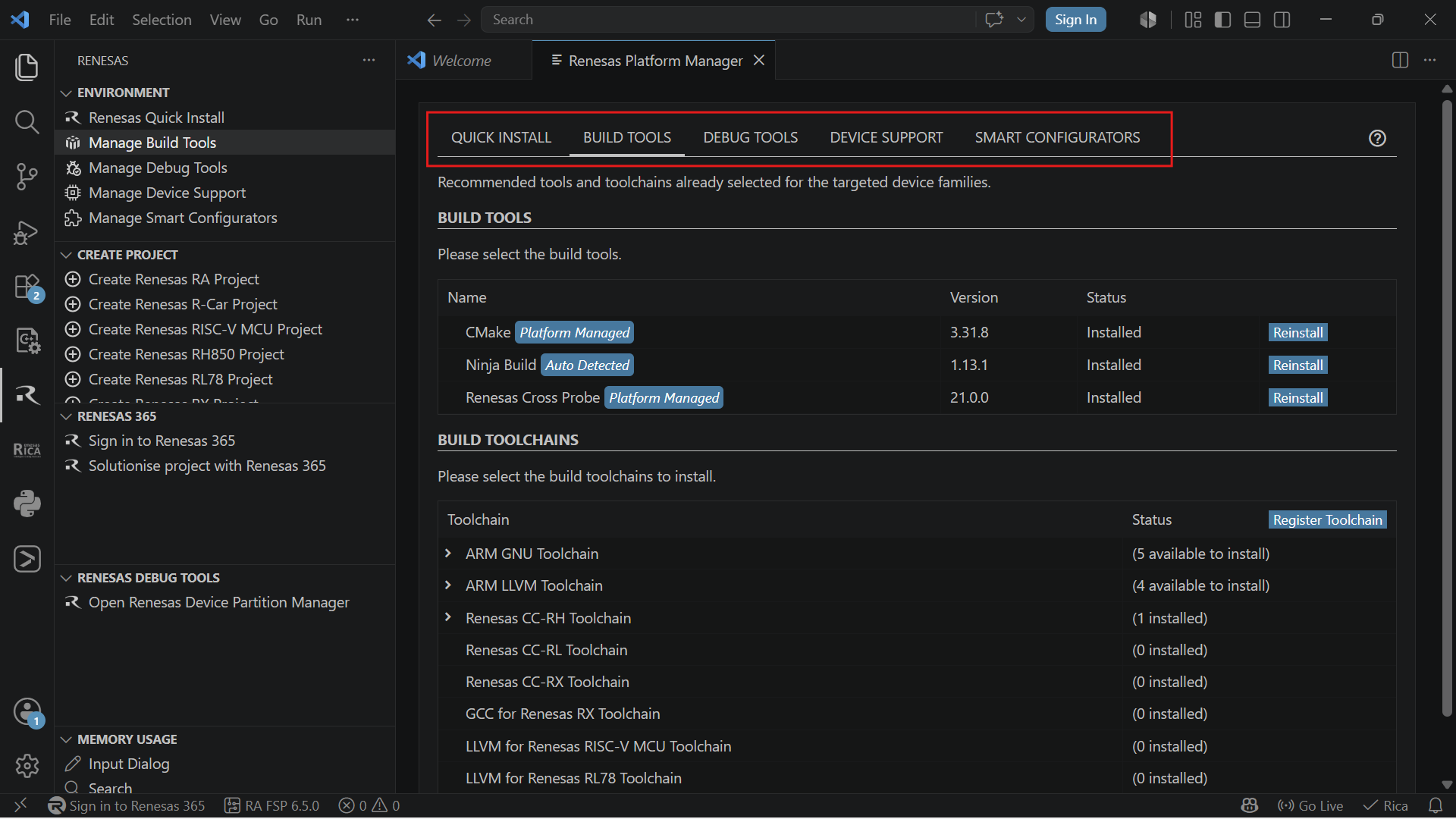
The installation plan automatically includes all the prerequisites. Moreover, you can also select additional tools or toolchain versions by checking the “Build Tools”, “Debug Tools”, “Device Support” and the “Smart Configurators” tabs.
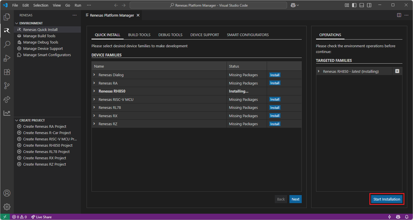
When your selection is ready, click the “Start Installations” button. The download and installation process will start automatically.
Installing the latest RH850 FSP Smart Configurator:
Download and install the latest version of RH850 FSP Smart Configurator:
After installing the Renesas RH850 FSP Smart Configurator, you should register the Renesas Smart Configurator installation in VS Code. In order to register the Renesas RH850 FSP Smart Configurator, perform the following steps:
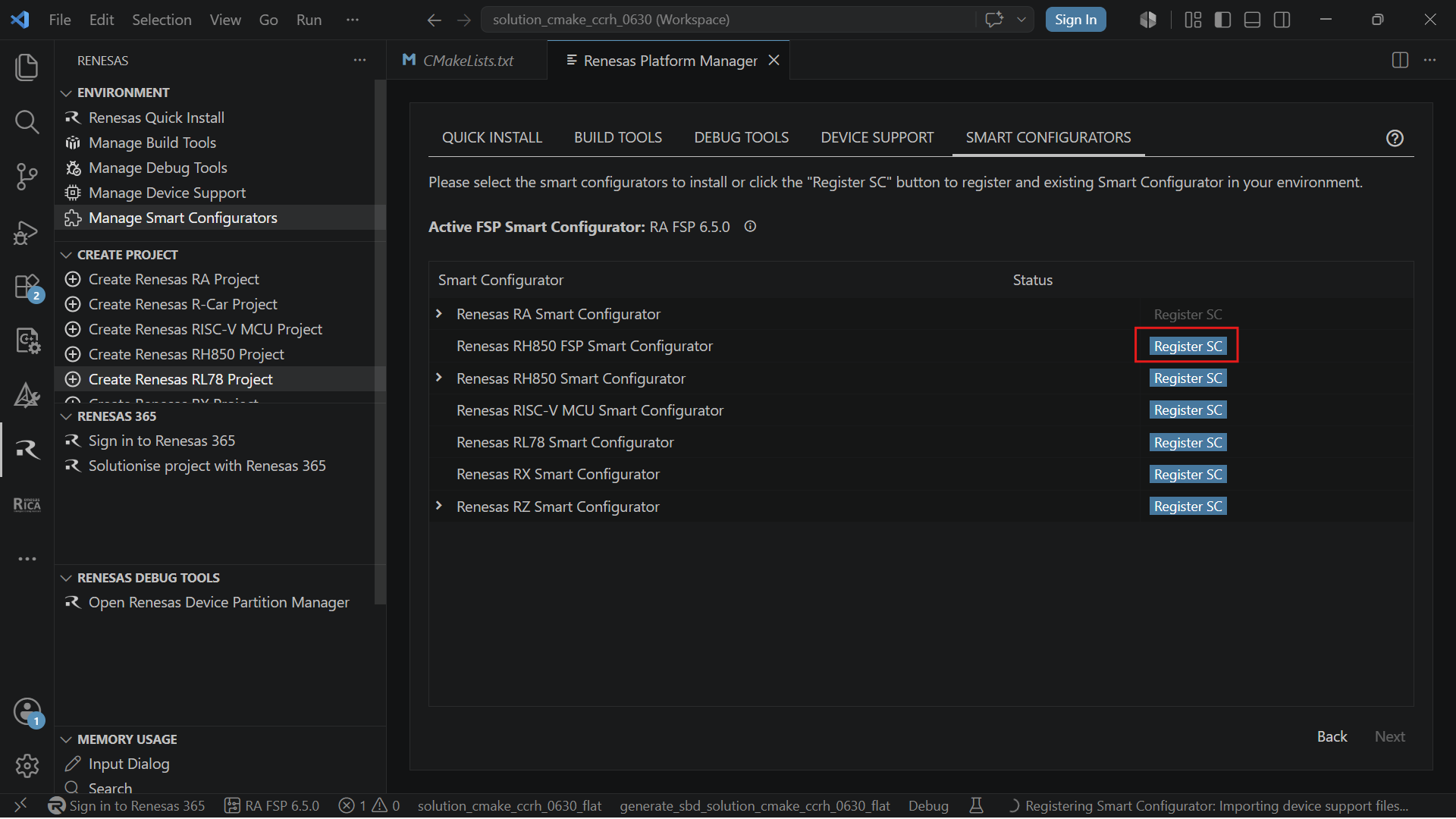
Click “Manage Smart Configurators” and check the Renesas RH850 FSP Smart Configurators. Use the “Register SC” button to register the Smart Configurator manually by selecting the path of the Smart Configurator.
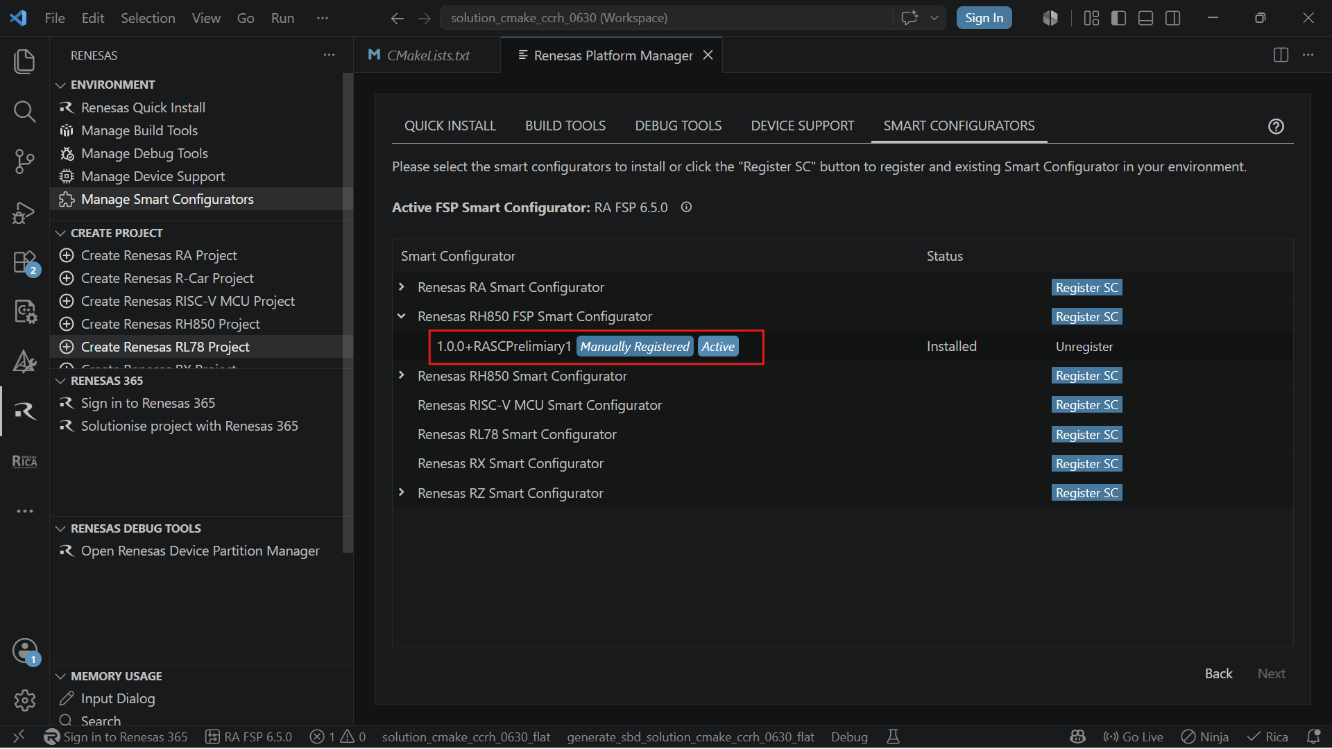
Once it is registered, the Smart Configurator will be visible in the Renesas RH850 FSP Smart Configurators list.
Adding System Environment Variable “RH850_CCRH_TOOLCHAIN_PATH” for “CC-RH” toolchains for RH850 FSP Project Build:
Use Windows Search to find and open [Edit the system environment variables]

In the [Advanced] tab, click on the [Environment Variables…] button to open the [Environment Variables] dialog.
Add a new variable by clicking “New…” for CCRH toolchain.
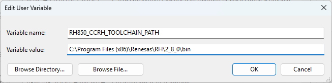
Note: after adding the environment variable, it is needed to close all VS Code and reopen them, otherwise, the environment variable will not work.
Installing Additional Emulator Drivers
You may need to download and install additional USB drivers for establishing a connection with the emulators and devices. Please install the latest drivers before starting your debug session. Use the following links to download the drivers suitable for your operating system and device:
16.3. Creating a Project
For RH850 FSP device family projects, it is recommended to use RH850 FSP Smart Configurator to create a project for VS Code. Smart Configurator can be accessed via the “Create Project” view in the “Renesas” tab. Please use the following instructions to create and build a project for RH850 FSP device family.
Navigate to “Renesas” and click [Create Renesas RH850 FSP project] from the commands.
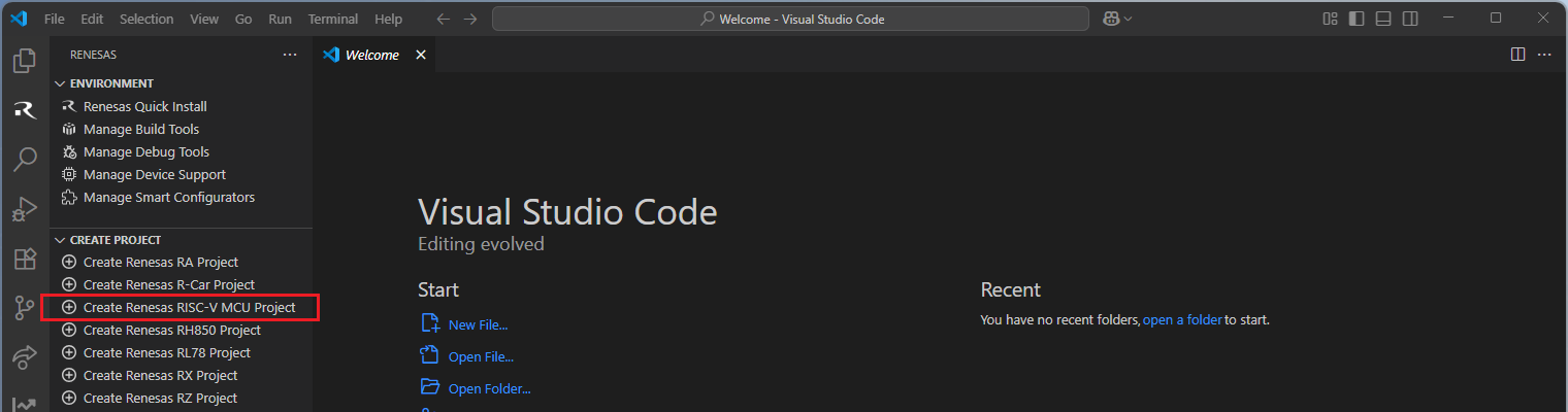
Select [Create RH850 FSP Project with Smart Configurator] option from the list.

Then, VSCode will show installed [RH850 FSP Smart Configurator] list, select a [Smart Configurator] from the list.

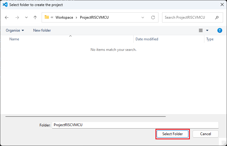
Select a [Folder] to create the project.
Keep the [Project name] and click [Next].
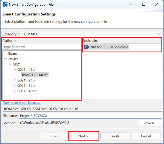
Configure your board, device type and preferred toolchain from the toolchains list, then click [Next].
Choose the “Smart Bundle” configuration and continue by clicking [Next] (Skip choosing the Smart Bundle selection for the sample project).
Choose the “RTOS” configuration and continue by clicking [Next] (Continue with “No RTOS” for the sample project).
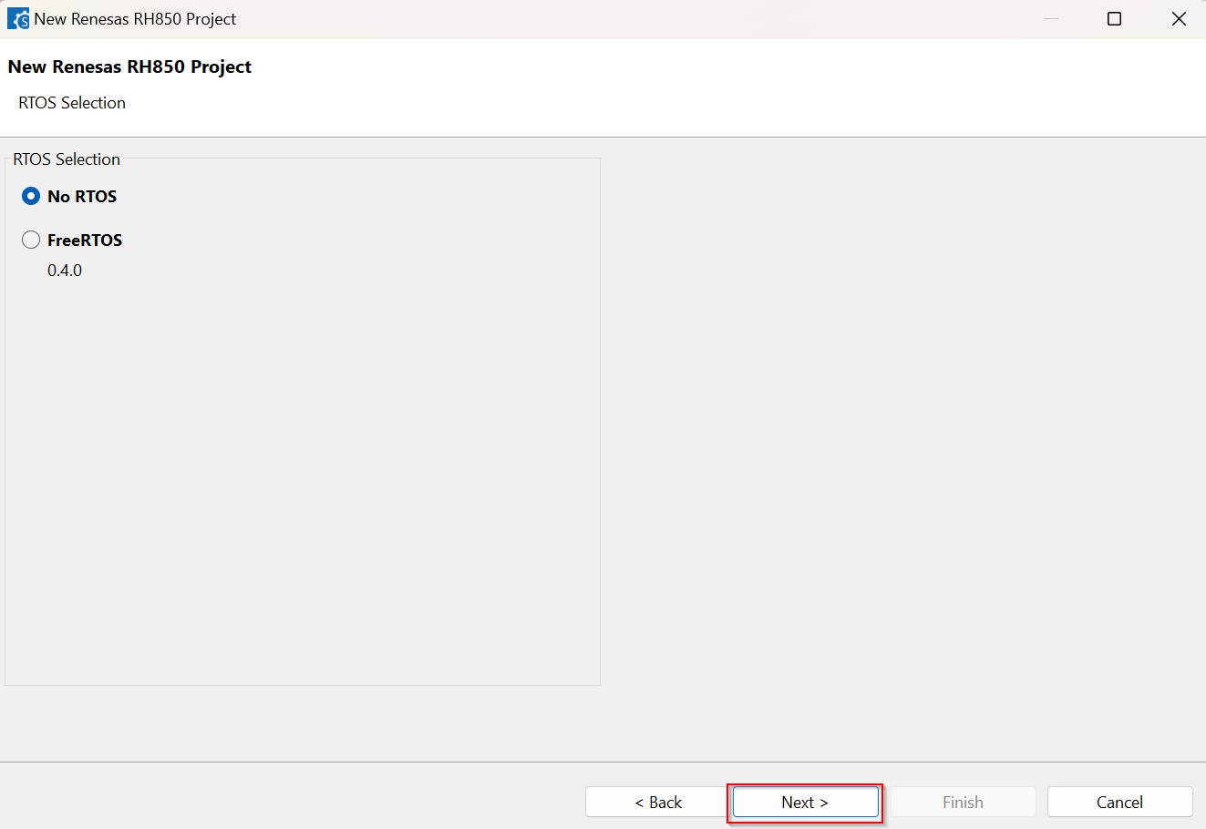
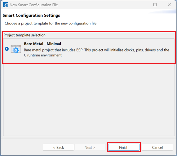
Choose one of the project templates then click [Finish] to complete the project creation steps.
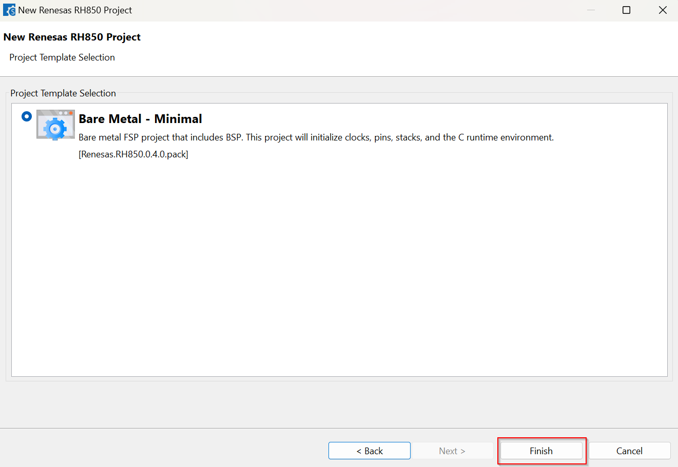
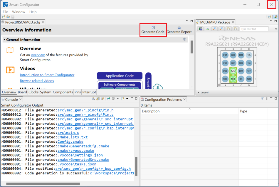
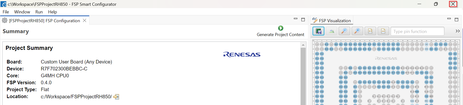
Close [RH850 FSP Smart Configurator] after generation of the project files completed.
16.4. Building the Project
For building a project, which has been created with RH850 FSP Smart Configurator, please follow the steps below:
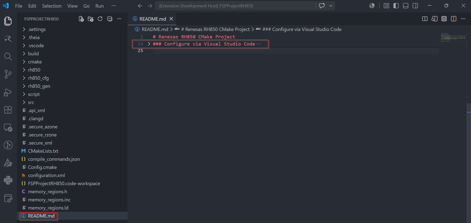
Please follow the Configure via Visual Studio Code section in README.md to set up the environment variables.
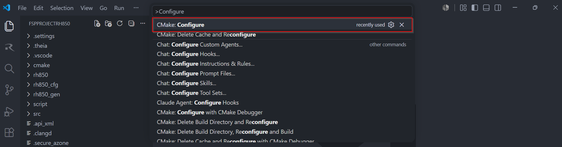
When the project is opened for the first time, CMake configure and the CMake Kit selection operations must be performed. In order to do these operations, open the “Command Palette” in VSCode and select “CMake: Configure” from the commands.
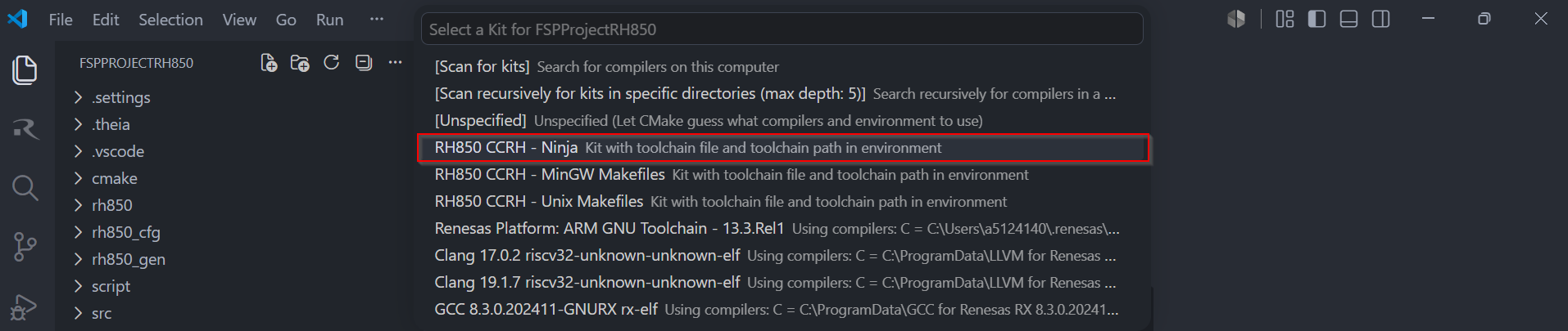
Then, a kit selection menu will be shown. Select “RH850 CCRH - Ninja” from the menu if the project is generated for CCRH toolchain, or, select “RH850 IAR_RH850 - Ninja” from the menu if the project is generated for IAR toolchain.
Note
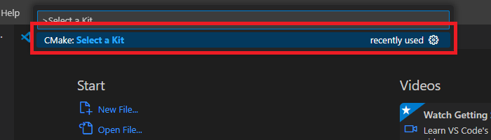
Missing the selection of the CMake Kit or selecting the wrong kit can cause build problems. If you missed the CMake Kit selection or selected the wrong kit, run “CMake: Select a Kit” from the VS Code Command Palette, select the correct Renesas Platform kit, and configure the project again.
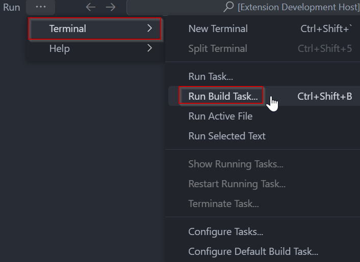
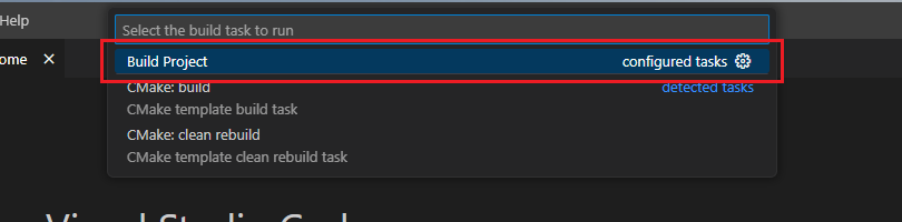
In VS Code, click [Terminal] ⇒ [Run Build Task] from the menu. Alternatively, press ctrl+shift+B to quickly open the Build task.
Select [Build Project] from the commands.
16.5. Editing/Re-configuring the Project
To edit a project, which has been created with RH850 FSP Smart Configurator, please follow the steps below:
Right click the “configuration.xml” file at the project root, and select the “Open with Smart Configurator” option in the context menu.
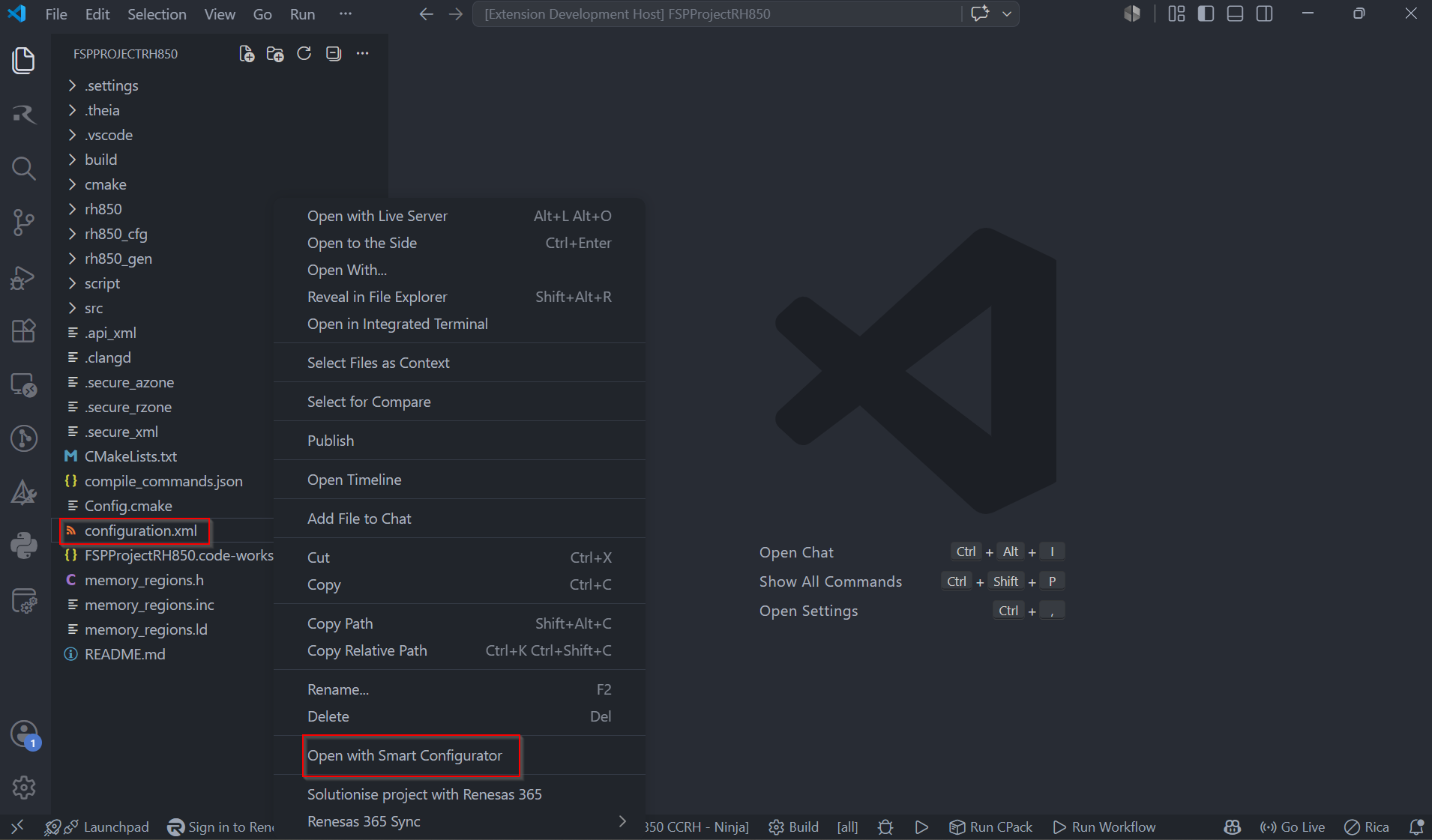
VSCode will show installed [RH850 FSP Smart Configurator] list, select a [Smart Configurator] from the list to open the project.

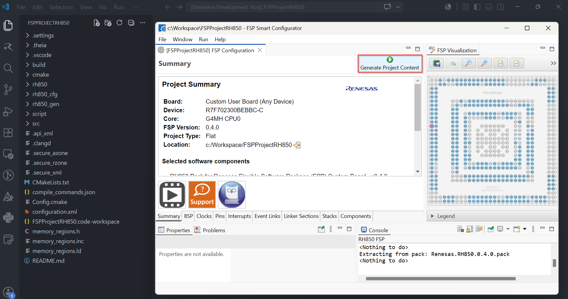
VSCode will open the project in the selected RH850 FSP Smart Configurator, now you can edit your project configuration in the RH850 FSP Smart Configurator. Once the changes completed, click the “Generate Project Content” button to re-generate the project content.
16.6. Debugging the Project
A debug session can be started by selecting the created configuration and clicking the [Start Debugging] button in the [Run and Debug] tab, or pressing [F5] from the keyboard.
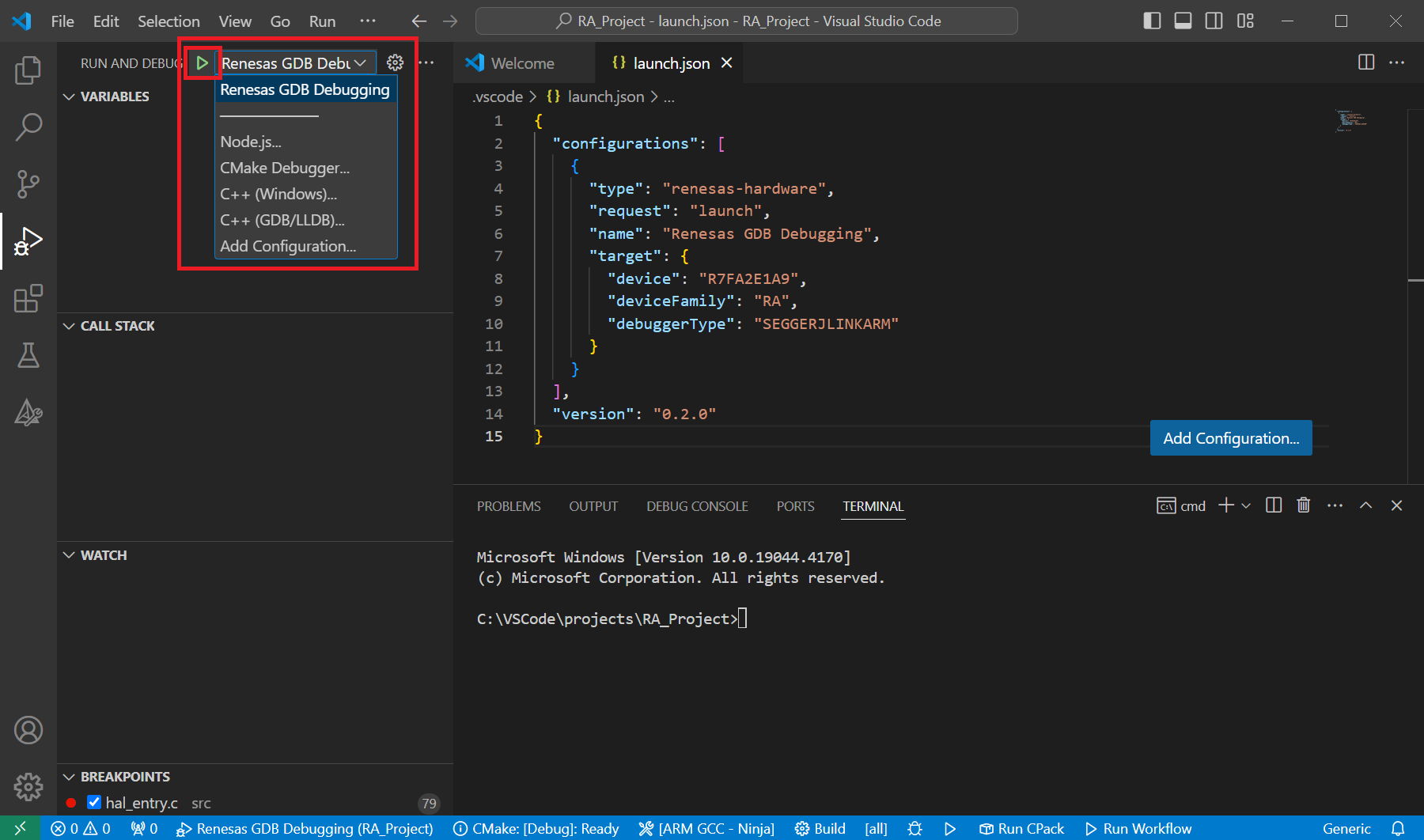
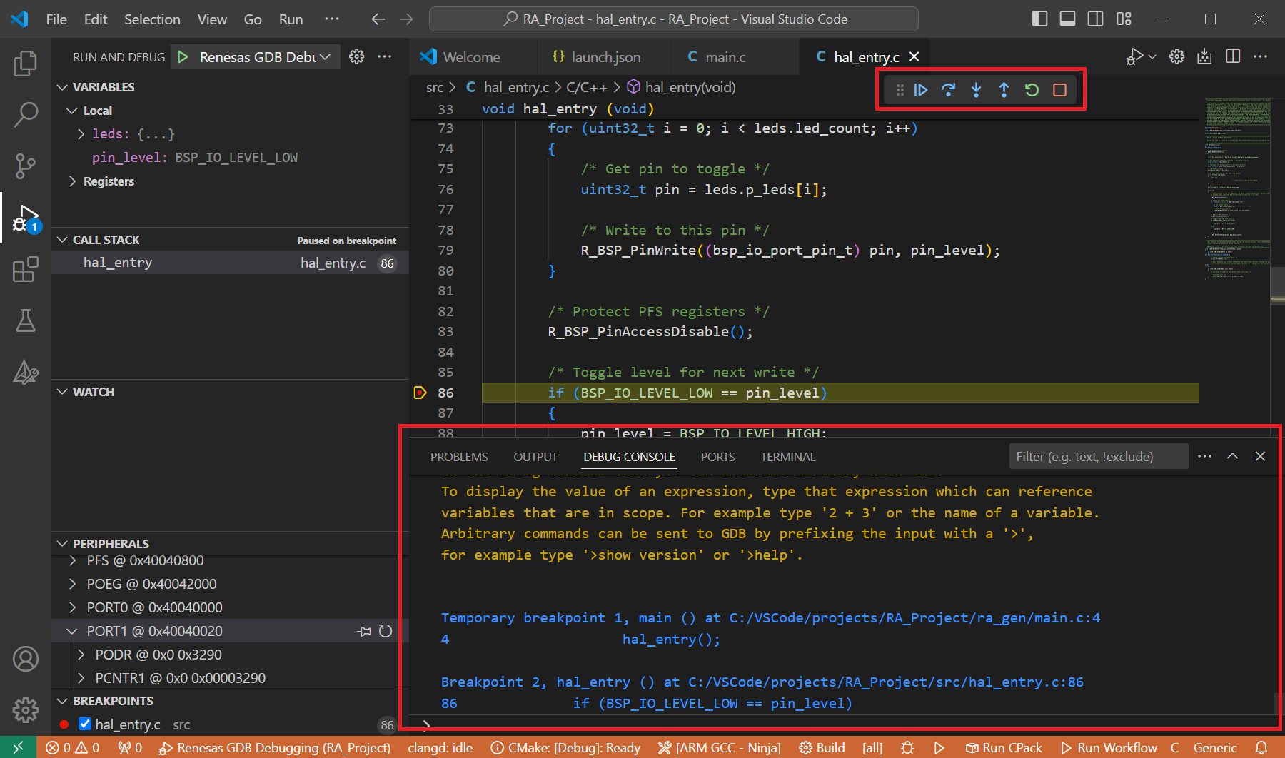
When VS Code starts the debug session, common debug control flow functions like resume, suspend, step into, step over, step out, restart, terminate debug session can be performed via the debug flow control buttons. Also, the [Debug Console] view will contain useful messages during the debug session.
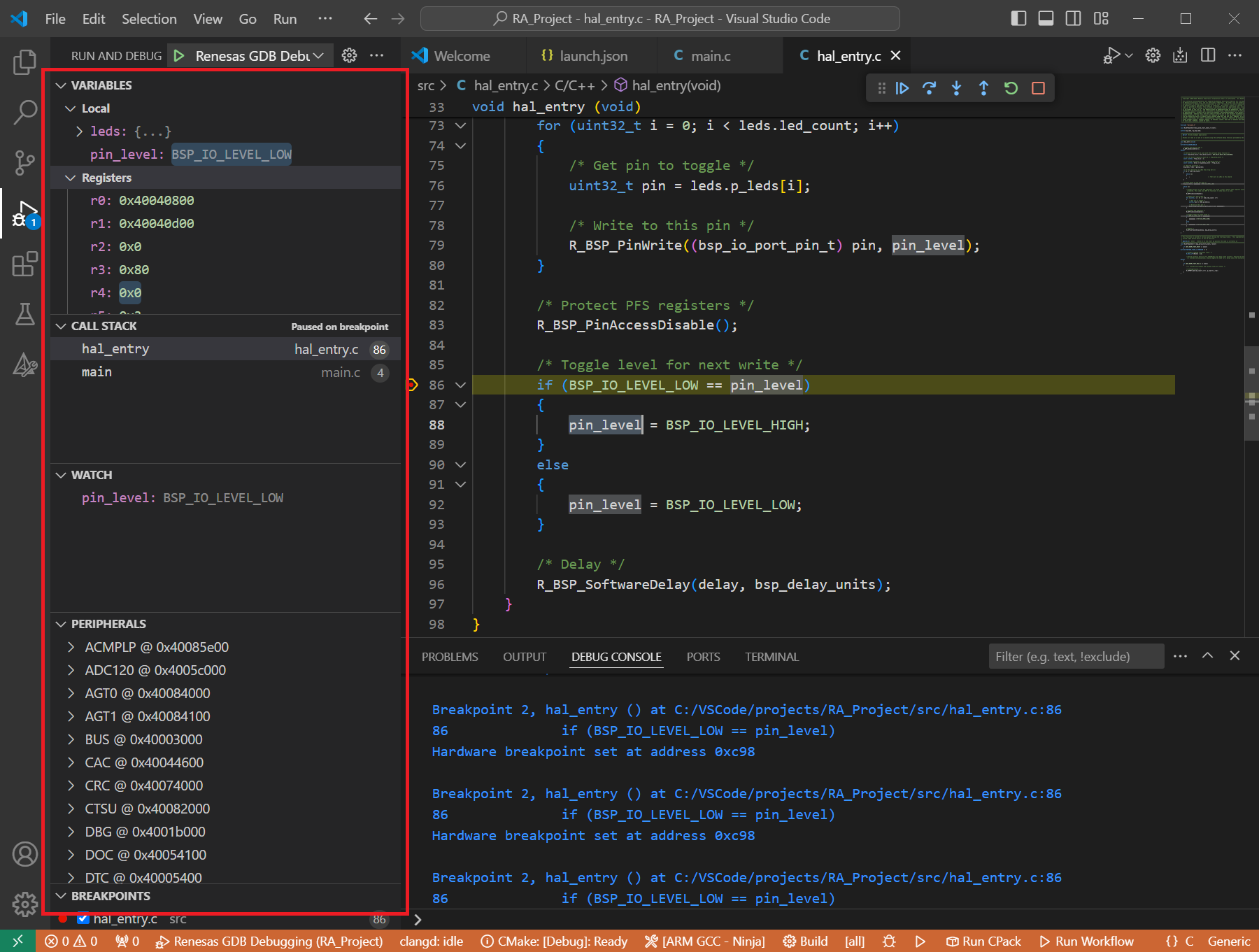
During the debug session, details about the local variables, device registers, call stack, watched variables, states of the peripherals can be accessed at the primary sidebar of VS Code in the [Run and Debug] tab.
16.7. GDB Server launch parameters for RH850 devices
Reference for common parameters: All common server parameters, including default settings and options applicable to Renesas device families, are documented in the GDB Server Parameters section. The specific parameters of the RH850 devices are described below.
16.7.1. Connection Settings
16.7.1.1. Clock
Option |
Details |
|---|---|
|
Description: Configure the Main Clock Frequency.
Default Value: Dependent on target device.
Emulator: E1, E2
Available Values: 0.0001 to 99.9999 (in MHz). Values up to the second decimal place.
Example:
"serverParameters": { "-umFreq=": 16.00 } |
16.7.1.2. Connection
Option |
Details |
|---|---|
|
Description: Specify the emulator serial number to be connected.
Default Values: Auto (Emulator will be selected automatically.)
Emulator: E1, E2
Available Values: Emulator information with format: <emulator type>:<serial number>
Example:
"serverParameters": { "-sn=": "e2:_9es002310c" } |
|
Description: Select the LPD mode for the connection.
Default Value: 4 (LPD 4-pin)
Emulator: E1, E2
Available Values:
-ulpdType= 0: LPD 1-pin-ulpdType= 4: LPD 4-pin-ulpdType= 15: JTag (E2 only)Example:
"serverParameters": { "-ulpdType=": 4 } |
|
Description: Configure the LPD Clock Frequency.
Default Value: Default
Emulator: E1, E2
Available Values: Default, 3000, 5500, 11000, 16500, 20000, 25000, 33000, 40000, or any value from 0 to 99999 (in kHz).
Example:
"serverParameters": { "-ulpdFreq=": 3000 } or "serverParameters": { "-ulpdFreq=": "Default" }Note: Not active if LPD 1-pin is selected for Connection Type.
|
|
Description: Configure the LPD Baud Rate.
Default Value: Default
Emulator: E1, E2
Available Values: Default, 500, 1000, 2000, or any value from 0 to 9999 (in Kbps).
Example:
"serverParameters": { "-ulpdBaud=": 1000 } or "serverParameters": { "-ulpdBaud=": "Default" }Note: Not active if LPD 4-pin is selected for Connection Type.
|
|
Description: Configure the JTag Clock Frequency.
Default Value: Default
Emulator: E2
Available Values: Default, 6250, 11000, 16500, 20000, or any value from 0 to 99999 (in kHz).
Example:
"serverParameters": { "-uJTagClockFreq=": 6250 } or "serverParameters": { "-uJTagClockFreq=": "Default" }Note: Available when JTag connection type is selected.
|
|
Description: Specify whether to change option bytes to LPD setting before connecting.
Default Value: 1
Emulator: E1, E2
Available Values: 0: No, 1: Yes
Example:
"serverParameters": { "-setOptJtagLpd=": 1 } |
|
Description: Specify whether to change option bytes to JTAG (Nexus I/F) setting before disconnecting. If No is selected, the option bytes after disconnect is the LPD I/F.
Default Value: 0
Emulator: E1, E2
Available Values: 0: No, 1: Yes
Example:
"serverParameters": { "-setOptJtagJtag=": 0 } |
|
Description: Specify if connecting to an already running target system.
Default Value: 0
Emulator: E2
Available Values: 0: No, 1: Yes
Example:
"serverParameters": { "-uHotPlug=": 0 } |
|
Description: Specifies whether to release the RESET before disconnecting from the target system.
Default Value: 0
Emulator: E2
Available Values: 0: No, 1: Yes
Example:
"serverParameters": { "-releaseReset=": 0 } |
|
Description: Specifies whether to debug the initial stop/standby mode.
Default Value: 0
Emulator: E2
Available Values: 0: No, 1: Yes
Example:
"serverParameters": { "-uInitialStop=": 0 } |
16.7.1.3. Power
Option |
Details |
|---|---|
|
Description: Select whether to supply power to the target board from emulator (MAX 200mA).
Default Value: 0
Emulator: E1, E2
Available Values:
-w 1: power target from emulator.-w 0: do not power target from emulator.Example:
"serverParameters": { "-w": 0 } |
|
Description: Select the power voltage supplied to the target board.
Default Value: 0 (3.3 V)
Emulator: E1, E2
Available Values:
-usupplyVoltage= 0: 3.3 V.-usupplyVoltage= 1: 5.5 V.Example:
"serverParameters": { "-usupplyVoltage=": 0 } |
16.7.1.4. Flash
Option |
Details |
|---|---|
|
Description: Specify the security ID (32 or 64 hex digits) for device boot.
Default Value:
FFFFFFFFFFFFFFFFFFFFFFFFFFFFFFFF (dependent on target device).Emulator: E1, E2
Available Values: 0 to FFFFFFFFFFFFFFFFFFFFFFFFFFFFFFFF (32 or 64 hex digits depending on device).
Example:
"serverParameters": { "-usecurityID=": "FFFFFFFFFFFFFFFFFFFFFFFFFFFFFFFF" }Note: Depending on the device, switches between 32 digits or 64 digits.
|
|
Description: Specify the security ID (64 hex digits) for access to internal code flash memory.
Default Value: None
Emulator: E1, E2
Available Values: 0 to FFFFFFFFFFFFFFFFFFFFFFFFFFFFFFFF (64 hex digits).
Example:
"serverParameters": { "-ucodeFlashID=": "FFFFFFFFFFFFFFFFFFFFFFFFFFFFFFFF" }Note: Depending on the device, this option may not be active.
|
|
Description: Specify the security ID (64 hex digits) for access to internal data flash memory.
Default Value: None
Emulator: E1, E2
Available Values: 0 to FFFFFFFFFFFFFFFFFFFFFFFFFFFFFFFF (64 hex digits).
Example:
"serverParameters": { "-udataFlashID=": "FFFFFFFFFFFFFFFFFFFFFFFFFFFFFFFF" }Note: Depending on the device, this option may not be active.
|
16.7.1.5. Security
Option |
Details |
|---|---|
|
Description: Specify whether to perform authentication in DLL format.
Default Value: 0
Emulator: E1, E2
Available Values: 0: No, 1: Yes
Example:
"serverParameters": { "-uneedAuthentication=": 0 } |
|
Description: Specify the full path of the authentication DLL file.
Default Value: None
Emulator: E1, E2
Available Values: Any valid file path.
Example:
"serverParameters": { "-uauthenticationDll=": "D:/dev_test/auth/authentication.dll" } |
16.7.1.6. SW-OPBT
Option |
Details |
|---|---|
|
Description: Set the Reset Vector for each core.
Default Value: None
Emulator: E2
Available Values: From 00000000 to FFFFFFFF.
Example:
"serverParameters": { "-uswOpbtRv=": "00000000" }Note: The number of parameters that need to be set depends on the target device.
|
|
Description: Set the OPBT value.
Default Value: None
Emulator: E2
Available Values: From 00000000 to FFFFFFFF.
Example:
"serverParameters": { "-uswOpbt=": "00000000" }Note: The number of parameters that need to be set depends on the target device.
|
|
Description: Set the ICUM OPBT value.
Default Value: None
Emulator: E2
Available Values: From 00000000 to FFFFFFFF.
Example:
"serverParameters": { "-uswOpbtIcum=": "00000000" }Note: The number of parameters that need to be set depends on the target device.
|
16.7.2. Debug Tool Settings
16.7.2.1. General Debug
Option |
Details |
|---|---|
|
Description: Select whether to reset the program after downloaded.
Default Value: 1
Emulator: E1, E2
Available Values: 0: No, 1: Yes
Example:
"serverParameters": { "-uresetOnReload=": 1 } |
16.7.2.2. Break
Option |
Details |
|---|---|
|
Description: Select whether to terminate peripheral emulation while stopping the program execution.
Default Value: 0
Emulator: E1, E2
Available Values: 0: No, 1: Yes
Example:
"serverParameters": { "-ustopPeriEmu=": 0 } |
16.7.2.3. Mask for Input Signal
Option |
Details |
|---|---|
|
Description: Configure Reset Signal Masking.
Default Value: 0
Emulator: E1, E2
Available Values: 0: No, 1: Yes
Example:
"serverParameters": { "-umaskReset=": 0 } |
|
Description: Configure the HLDRQ Signal Masking.
Default Value: 0
Emulator: E1, E2
Available Values: 0: No, 1: Yes
Example:
"serverParameters": { "-umaskHldrq=": 0 } |
|
Description: Configure STOP Signal Masking.
Default Value: 0
Emulator: E1, E2
Available Values: 0: No, 1: Yes
Example:
"serverParameters": { "-umaskStop=": 0 } |
|
Description: Configure WAIT Signal Masking.
Default Value: 0
Emulator: E1, E2
Available Values: 0: No, 1: Yes
Example:
"serverParameters": { "-umaskWait=": 0 } |
16.7.2.4. Memory
Option |
Details |
|---|---|
|
Description: Configure Memory Map mode.
Default Value: 0
Emulator: E2
Available Values: 0: Single map mode, 1: Double map mode
Example:
"serverParameters": { "-uMapMode=": 0 } |
|
Description: Configure if verify on write to memory is enabled.
Default Value: 0
Emulator: E1, E2
Available Values: 0: No, 1: Yes
Example:
"serverParameters": { "-uverifyOnWritingMemory=": 0 } |
|
Description: Specify the first address of the working RAM area for use by the debugger.
Default Value: Dependent on target device.
Emulator: E1, E2
Available Values: Any valid hex address.
Example:
"serverParameters": { "-uWorkRamAddress=": "0x20000000" } |
|
Description: Specifies whether to debug with Code SRAM.
Default Value: 0
Emulator: E1, E2
Available Values: 0: No, 1: Yes
Example:
"serverParameters": { "-uDebugCodeSRAM=": 0 } |
|
Description: Select whether to initialize RAM when connecting.
Default Value: 1
Emulator: E1, E2
Available Values: 0: No, 1: Yes
Example:
"serverParameters": { "-uInitialiseRAM=": 1 } |
16.7.2.5. Performance Timer
Option |
Details |
|---|---|
|
Description: Specify the operating frequency used to calculate the performance counter.
Default Value: None
Emulator: E1, E2
Available Values: Between 0.001 to 999.999 (in MHz). Value is converted to Hz internally.
Example:
"serverParameters": { "-uPTimerClock=": 16.00 }Note: It is possible to specify an empty value.
|
16.7.2.6. Reset With Running
Option |
Details |
|---|---|
|
Description: Use forced reset for the reset process during execution
Default Value: 0
Emulator: E1, E2
Available Values: 0: No, 1: Yes
Example:
"serverParameters": { "-uForceReset=": 0 } |
16.7.3. Multiple Core Settings
Option |
Details |
|---|---|
|
Description: Specify the state of the core. The displayed core name depends on the target device.
Default Value: Enabled
Emulator: E1, E2
Available Values: Enabled, Disabled, Free running.
Example:
"serverParameters": { "-uCore=": "PE1|enable|256|main" }Note: The value sent to GDB server follows the format
<core name>|<state>|<value>|<type>(e.g.
PE1|enable|256|main when PE1 is set to Enabled).When multiple cores are enabled, each core is sent as a separate
-uCore= parameter,for example:
"-uCore=": "PE1|enable|256|main""-uCore=": "PE2|enable|257|main"This parameter is not sent to GDB server when Disabled or Free running is selected. Availability dependent on the target and debugger support, and more than one core being enabled.
|
|
Description: Specify the synchronization mode of the cores.
Default Value: async
Emulator: E1, E2
Available Values: async, sync
Example:
"serverParameters": { "-uSyncMode=": "async" }Note: Availability dependent on the target and debugger support, and more than one core being enabled.
|
|
Description: Specify the trace data capture target. When running with a single core, only the trace information of the specified core is displayed in the Trace view.
Default Value: PE1 (Dependent on the target device)
Emulator: E1, E2
Available Values: Any valid enabled core name (e.g. PE1, PE2).
Example:
"serverParameters": { "-uTraceCore=": "PE1" } |
16.7.4. Trace
Option |
Details |
|---|---|
|
Description: Select the core for which trace data is collected.
The displayed core name depends on the target device.
Default Value: Enabled
Emulator: E1, E2
Available Values: Enabled, Disabled.
Example:
"serverParameters": { "-uTraceEnable=": "PE1|PE2" }Note: The parameter value contains the list of enabled cores separated by
|. Only cores set to Enabled are included in the parameter value.For example, if PE1 and PE2 are both Enabled, the value is
"PE1|PE2". If only PE1 is Enabled, the value is "PE1". |
|
Description: Set the CPU clock frequency in MHz to calculate trace timestamps.
The displayed core name depends on the target device.
Default Value: Depends on target device.
Emulator: E1, E2
Available Values: 1.0 to 9999.999 (in MHz).
Example:
"serverParameters": { "-uTraceClock=": "PE1|400.0|PE2|400.0" }Note: The parameter value contains pairs of core name and clock frequency separated by
|. Only cores set to Enabled are included in the parameter value.For example, if PE1 is 400.0 MHz and PE2 is 200.0 MHz, the value is
"PE1|400.0|PE2|200.0". If only PE1 is Enabled, the value is "PE1|400.0". |
|
Description: Synchronize trace data across cores.
Default Value: 0
Emulator: E1, E2
Available Values:
-uUseSyncTrace= 1: Yes — synchronize trace data across cores.-uUseSyncTrace= 0: No — do not synchronize trace data.Example:
"serverParameters": { "-uUseSyncTrace=": 0 } |
|
Description: Select the synchronization trace target standard for cross-core trace data.
Default Value: 0 - E2 Expansion (master)
Emulator: E1, E2
Available Values:
-uSyncTraceStandard= 0: E2 Expansion (master).-uSyncTraceStandard= 1: E2 Expansion (slave).-uSyncTraceStandard= 2: STM.Example:
"serverParameters": { "-uSyncTraceStandard=": 0 } |
|
Description: Configure whether to use ERAM trace.
Default Value: 0
Emulator: E1, E2
Available Values: 0: No, 1: Yes
Example:
"serverParameters": { "-uUseEramTrace=": 0 }Note: This option is supported only for RH850 U2B (without E) device
|
|
Description: Set the start address of the ERAM area used for ERAM trace.
Default Value: Depends on target device.
Emulator: E1, E2
Available Values: ERAM areas enabled on the target device.
Example:
"serverParameters": { "-uEramAddress=": "0x20000000" }Note: This option is supported only for RH850 U2B (without E) device
|