20. Quick Start for Renesas RX FSP
20.1. Supported Environments
Operating System |
Windows: Windows 10 / Windows 11 |
VS Code version |
1.102.0 (minimum) |
VS Code can be downloaded and installed from this page https://code.visualstudio.com/.
20.2. Installation
Please choose your operating system for operating system dependent installation steps.
For the Renesas RX Family, Renesas Platform provides a straightforward installation wizard to install the CMake, Ninja, Python and the Support Files for RX Family. To set up your environment:
Open VS Code.
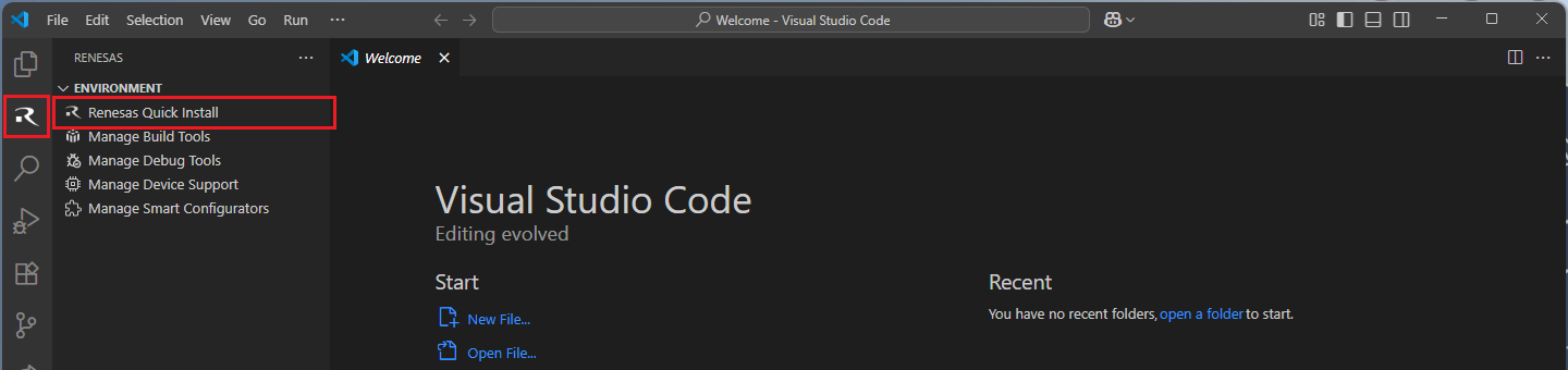
Navigate to the “Renesas” tab in VS Code. Then, click “Renesas Quick Install” in the “Environment” view.
Click the “Install” button for the “Renesas RX” device family. The Renesas Platform will now check the dependencies required by the Renesas RX Device Family. The Renesas Platform extension will check the local environment and CMake, Ninja, Python and the Support Files for RX Family, then create an installation plan for them if necessary.

The installation plan automatically includes all the prerequisites. Moreover, you can also select additional tools or toolchain versions by checking the “Build Tools”, “Debug Tools”, “Device Support” and the “Smart Configurators” tabs.
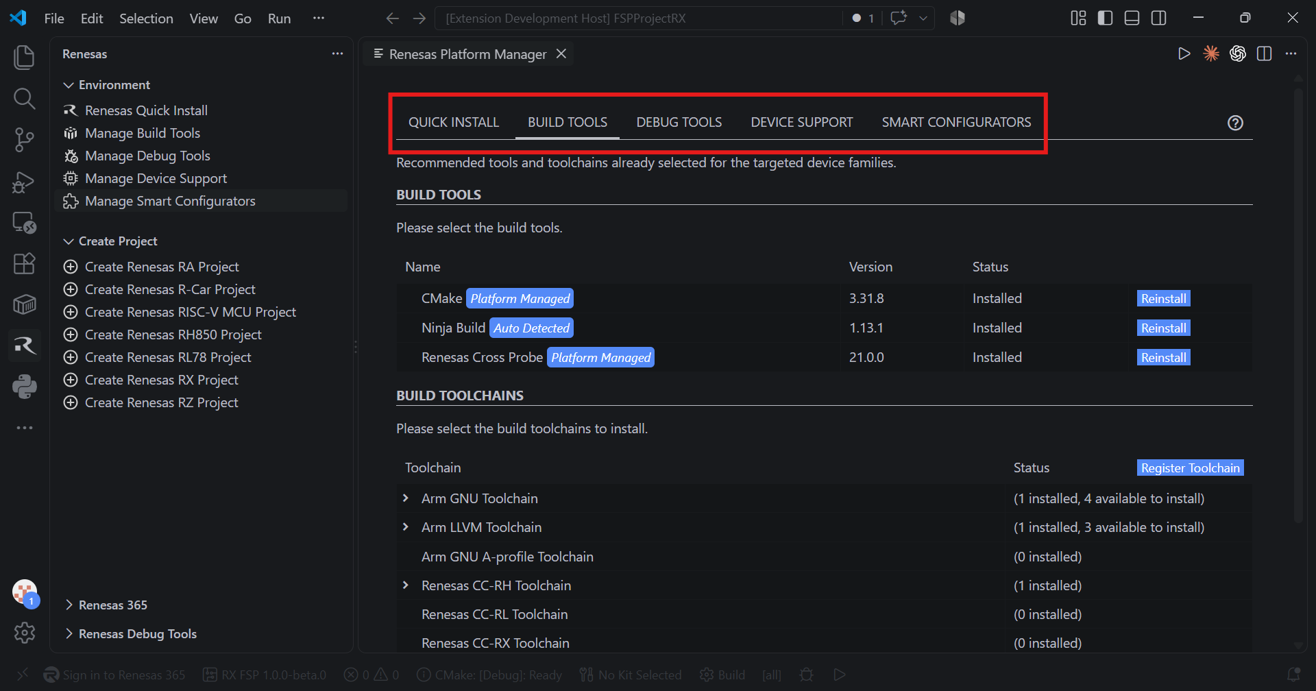
When your selection is ready, click the “Start Installations” button. The download and installation process will start automatically.

Installing the latest RX FSP Smart Configurator:
Download and install the latest version of RX FSP Smart Configurator:
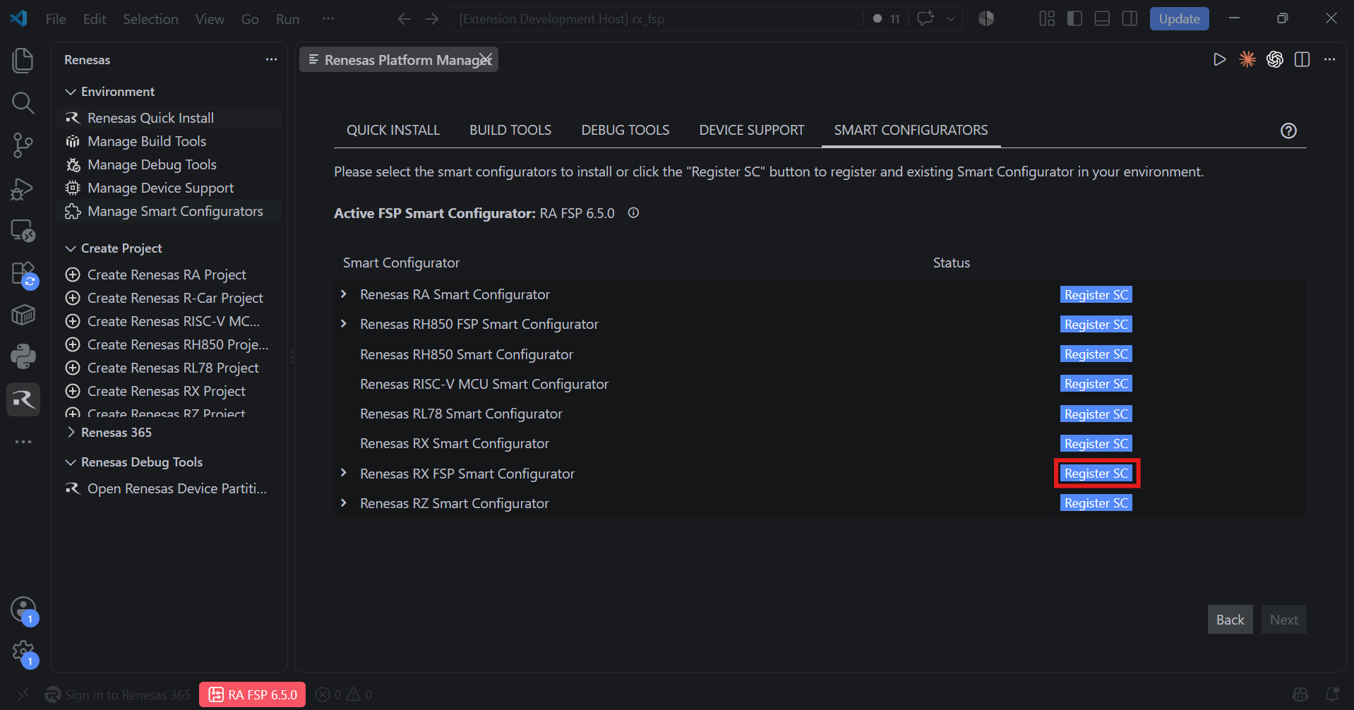
After installing the Renesas RX FSP Smart Configurator, you should register the Renesas Smart Configurator installation in VS Code. In order to register the Renesas RX FSP Smart Configurator, perform the following steps:
Click “Manage Smart Configurators” and check the Renesas RX FSP Smart Configurators. Use the “Register SC” button to register the Smart Configurator manually by selecting the path of the Smart Configurator.
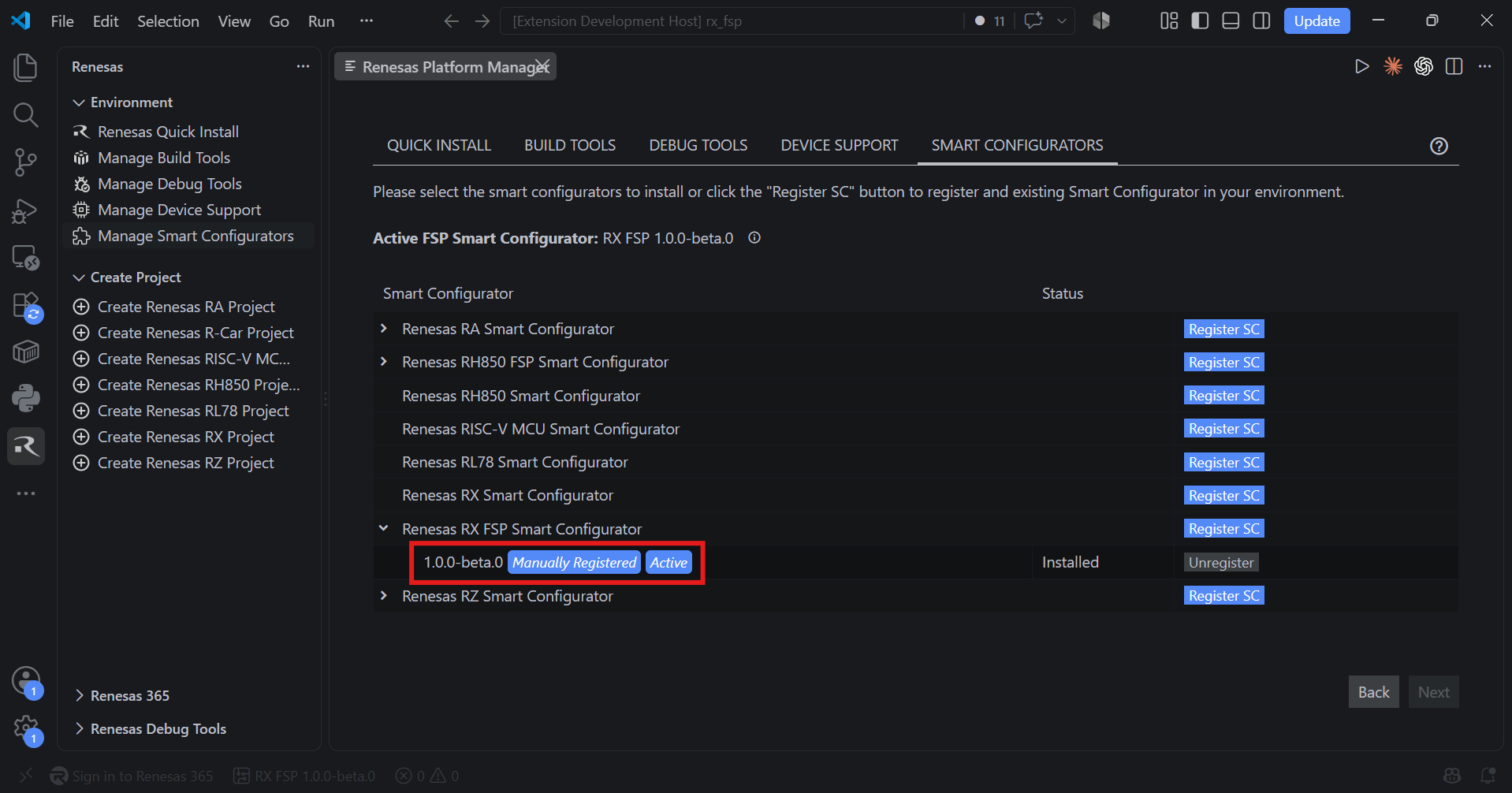
Once it is registered, the Smart Configurator will be visible in the Renesas RX FSP Smart Configurators list.
Installing Toolchains for RX Development:
Install one of the preferred toolchains for RX Project Build. It is recommended to use either “CC-RX” or “GCC for Renesas GNURX”.
Installing and Configuring “CC-RX” toolchain
For installing “CC-RX”:
Download and install the latest toolchain:
https://www.renesas.com/us/en/software-tool/cc-compiler-package-rx-family
Note
CC-RX toolchain should be installed to a path that does not contain spaces or special characters.
Add “CC-RX” toolchain to Renesas Platform
Registering CC-RX toolchain in Renesas Platform
Open VS Code
Navigate to the “Renesas” tab in VS Code and click “Manage Build Tools”.
Click the “Register Toolchain” button in the Build Toolchains table header.
In the folder selection dialog, navigate to the root folder of the CC-RX toolchain (not the
binfolder).Select the folder and complete the toolchain registration.
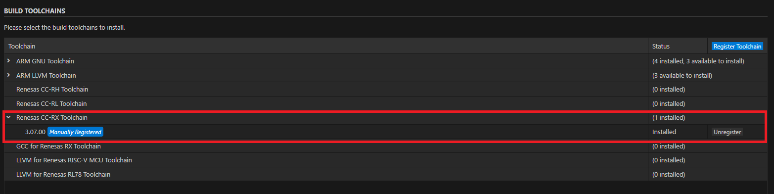
Installing and Configuring “GCC for Renesas GNURX” toolchain
For installing “GCC for Renesas GNURX”:
Download and install the latest toolchain:
https://llvm-gcc-renesas.com/rx-download-toolchains/
Note
GCC-RX toolchain should be installed to a path that does not contain spaces or special characters.
Add “GCC-RX” toolchain to Renesas Platform
Registering GCC-RX toolchain in Renesas Platform
Open VS Code
Navigate to the “Renesas” tab in VS Code and click “Manage Build Tools”.
Click the “Register Toolchain” button in the Build Toolchains table header.
In the folder selection dialog, navigate to the root folder of the GCC-RX toolchain (not the
binfolder).Select the folder and complete the toolchain registration.
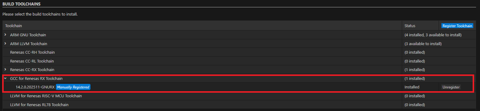
Installing Additional Emulator Drivers
You may need to download and install additional USB drivers for establishing a connection with the emulators and devices. Please install the latest drivers before starting your debug session. Use the following links to download the drivers suitable for your operating system and device:
For other Renesas emulators, please check for any recommended drivers:
20.3. Creating a Project
For RX FSP device family projects, it is recommended to use RX FSP Smart Configurator to create a project for VS Code. Smart Configurator can be accessed via the “Create Project” view in the “Renesas” tab. Please use the following instructions to create and build a project for RX FSP device family.
Navigate to “Renesas” and click [Create Renesas RX FSP project] from the commands.
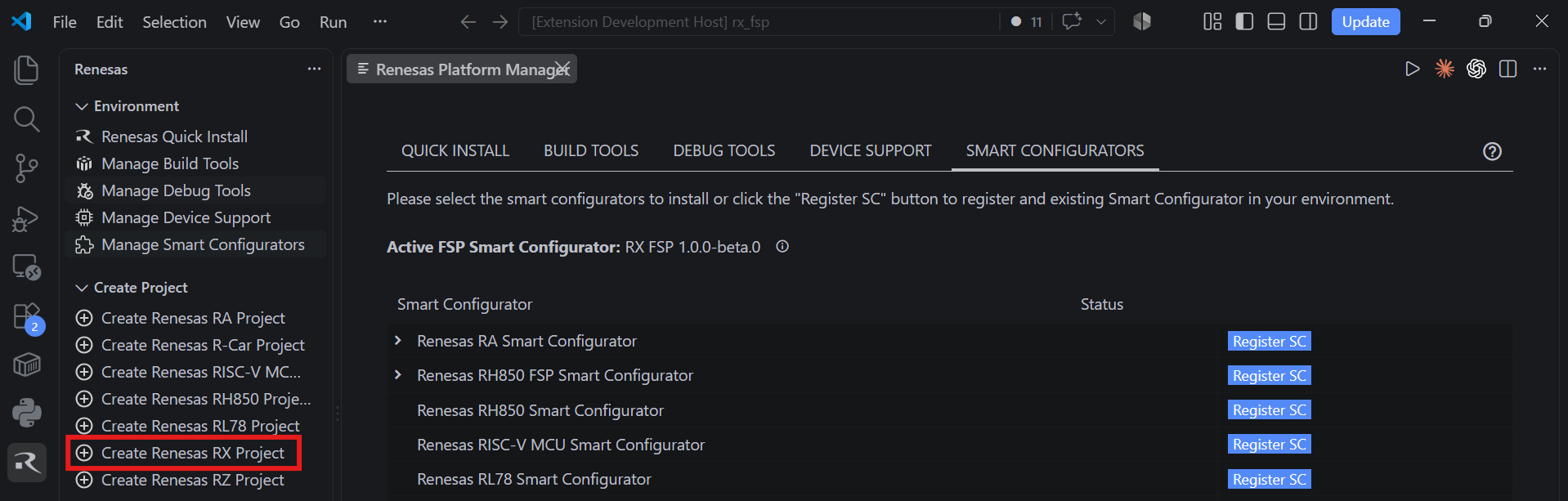
Select [Create RX FSP Project with Smart Configurator] option from the list.
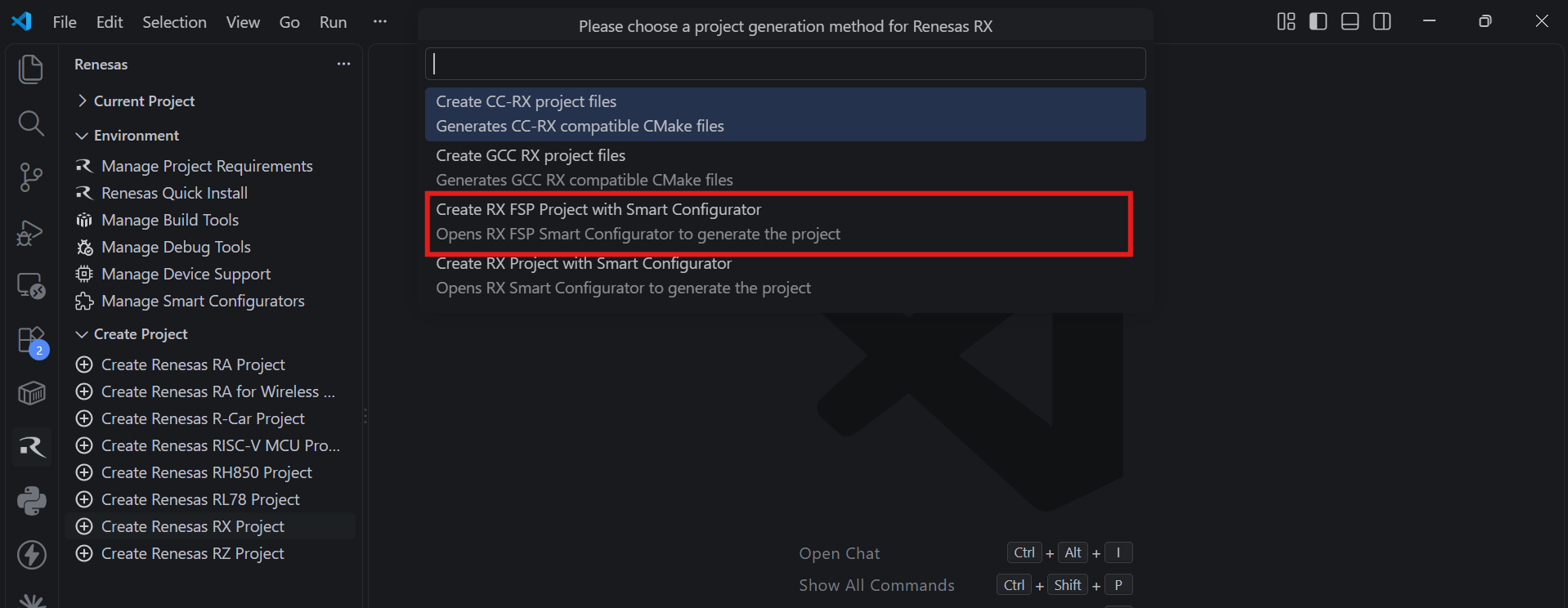
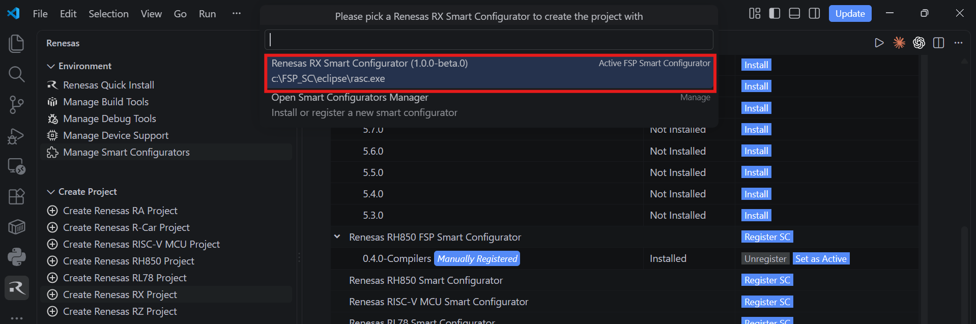
Then, VSCode will show installed [RX FSP Smart Configurator] list, select a [Smart Configurator] from the list.
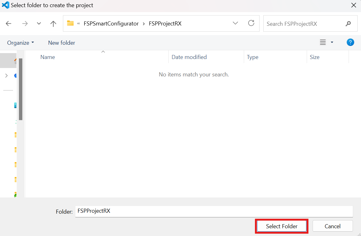
Select a [Folder] to create the project.
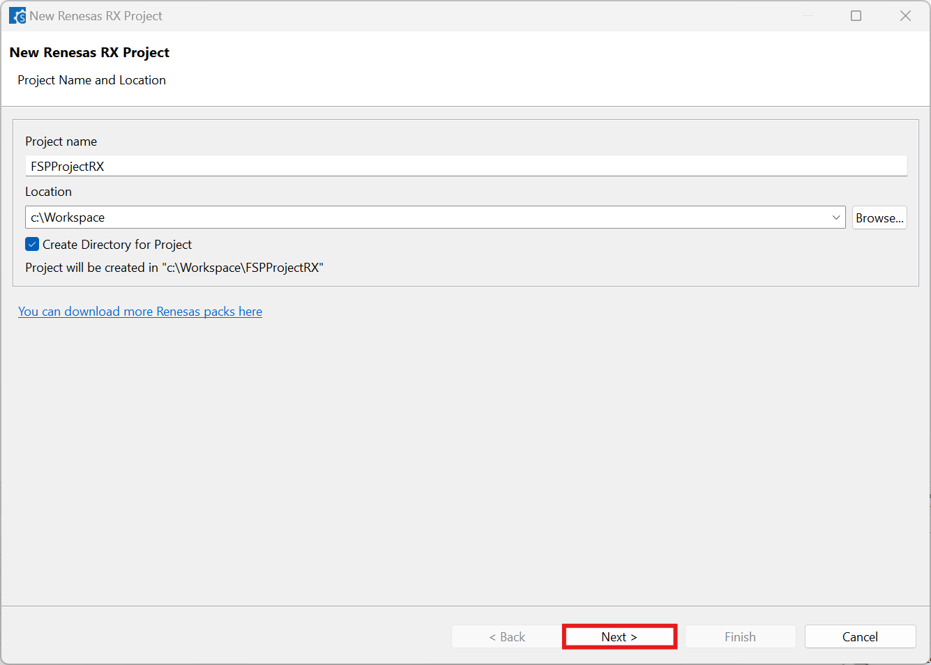
Keep the [Project name] and click [Next].
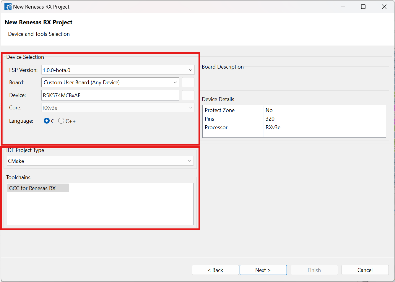
Configure your board, device type and preferred toolchain from the toolchains list, then click [Next].
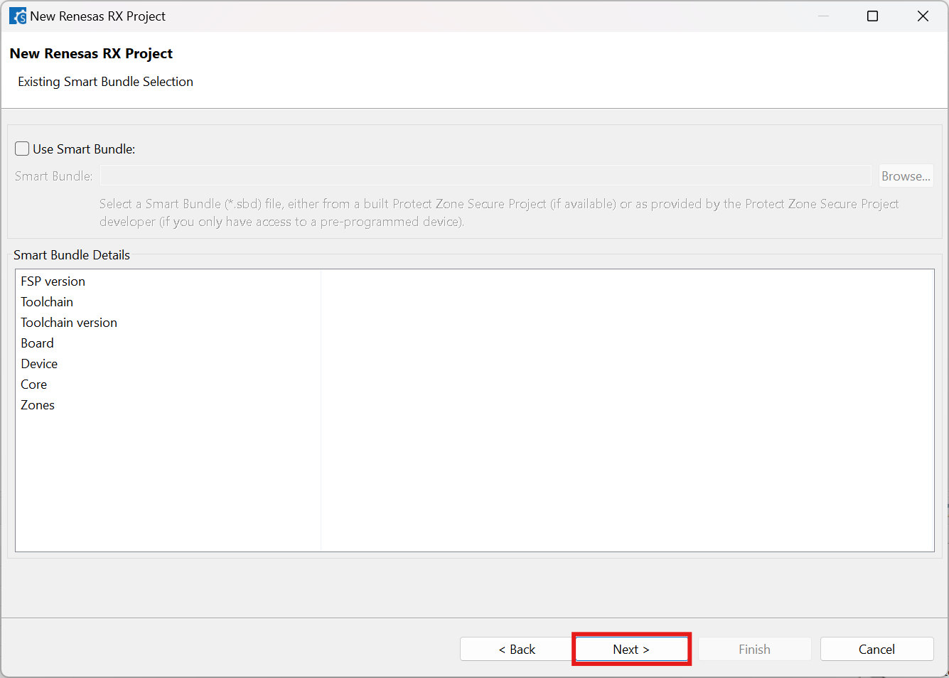
Choose the “Smart Bundle” configuration and continue by clicking [Next] (Skip choosing the Smart Bundle selection for the sample project).
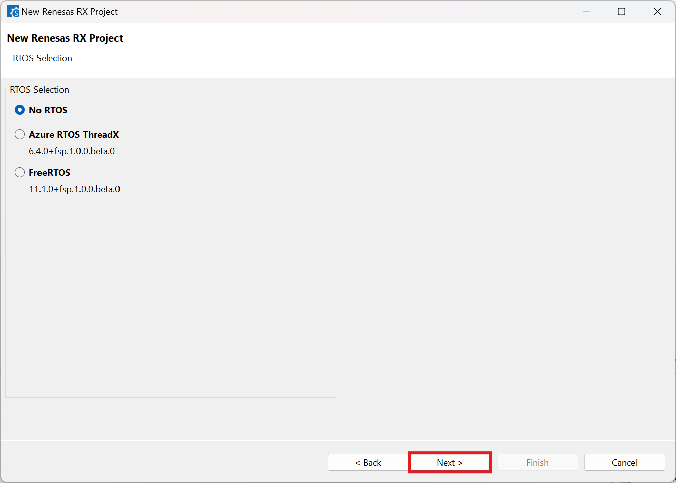
Choose the “RTOS” configuration and continue by clicking [Next] (Continue with “No RTOS” for the sample project).
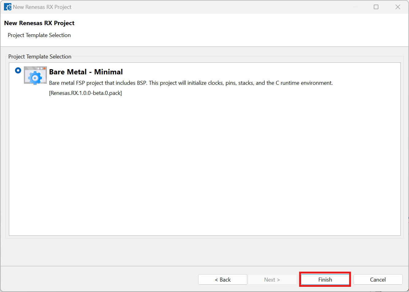
Choose one of the project templates then click [Finish] to complete the project creation steps.
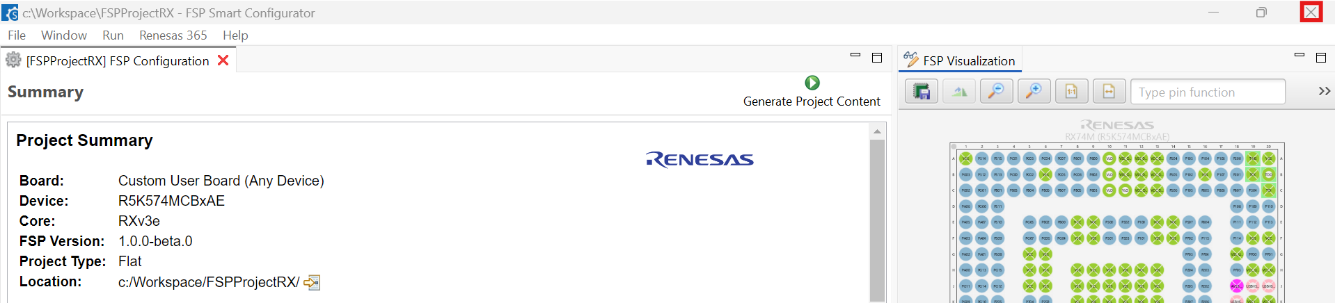
Close the [RX FSP Smart Configurator] once project generation completes.
20.4. Building the Project
To build a project created with RX FSP Smart Configurator, follow these steps:
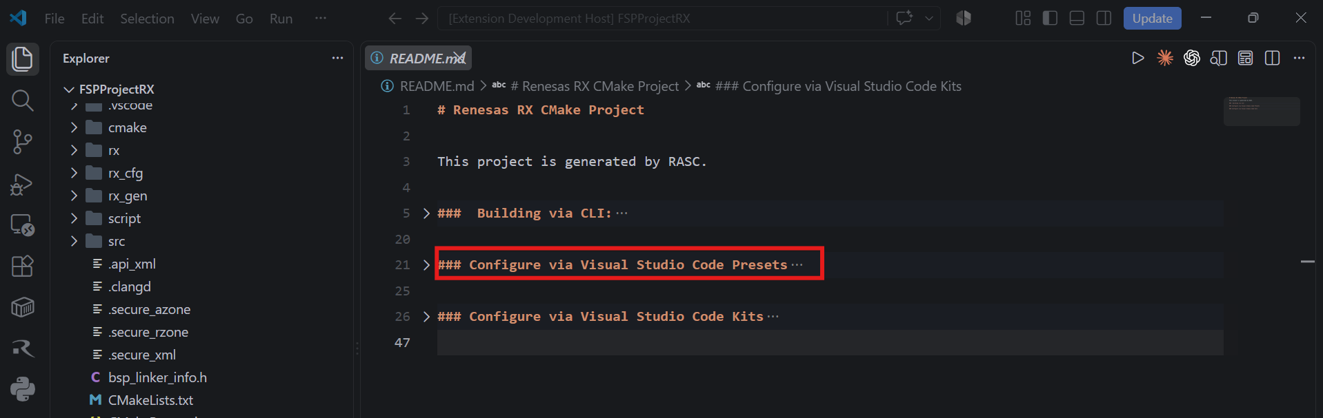
Open README.md in the generated RX FSP project and follow the Configure via Visual Studio Code Kits section for the selected toolchain.
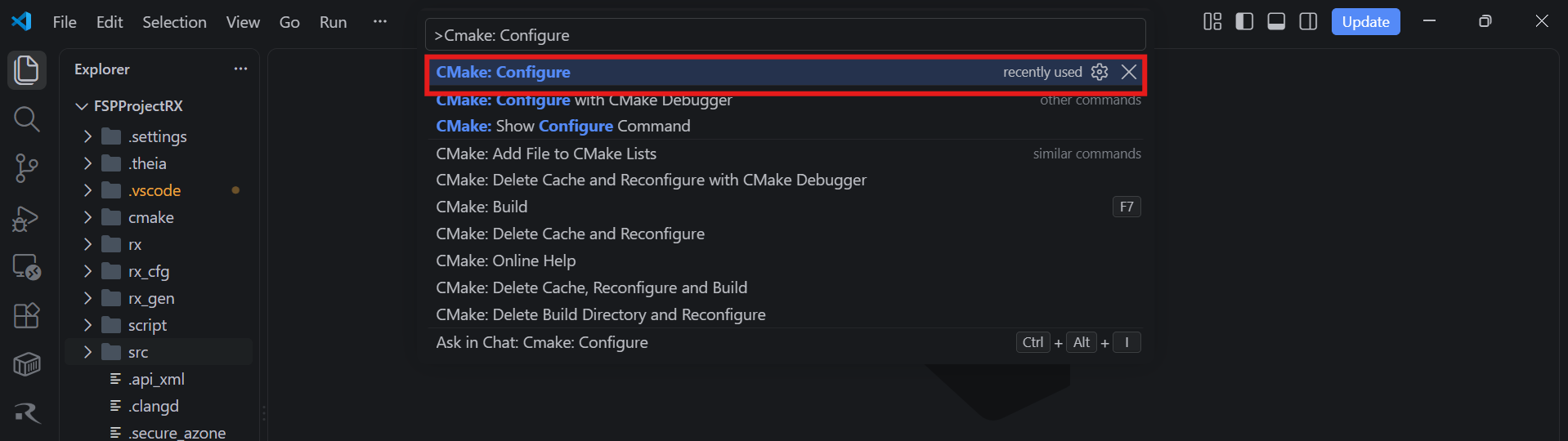
When the project is opened for the first time, CMake configure and the CMake Kit selection operations must be performed. In order to do these operations, open the “Command Palette” in VS Code and select “CMake: Configure” from the commands.
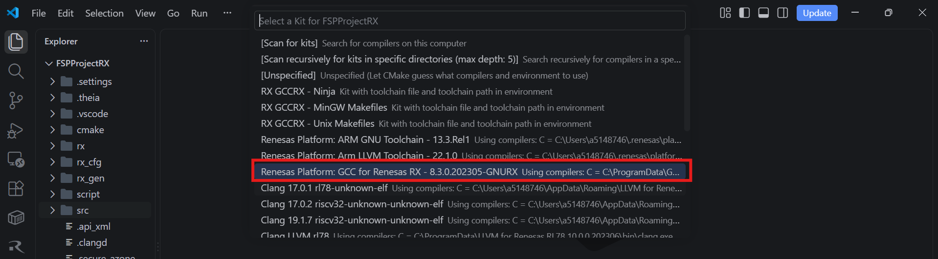
Then, a kit selection menu will be shown. Select the Renesas Platform kit that matches the toolchain used to generate the RX FSP project:
For CC-RX, select the kit whose name starts with “Renesas Platform: Renesas CC-RX Toolchain”.
For GCC-RX, select the kit whose name starts with “Renesas Platform: GCC for Renesas RX”.
Note
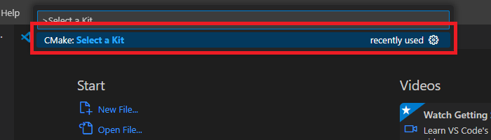
Missing the selection of the CMake Kit or selecting the wrong kit can cause build problems. If you missed the CMake Kit selection or selected the wrong kit, run “CMake: Select a Kit” from the VS Code Command Palette, select the correct Renesas Platform kit, and configure the project again.
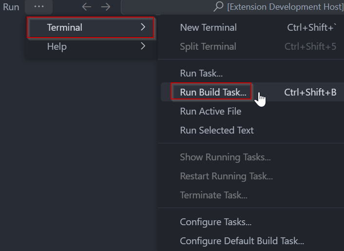
In VS Code, click [Terminal] ⇒ [Run Build Task] from the menu. Alternatively, press ctrl+shift+B to quickly open the Build task.
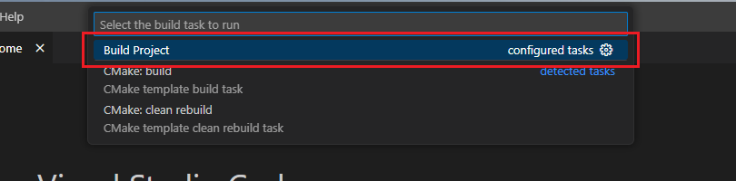
Select [Build Project] from the commands.
20.5. Editing/Re-configuring the Project
To edit an RX FSP Smart Configurator project, follow these steps:
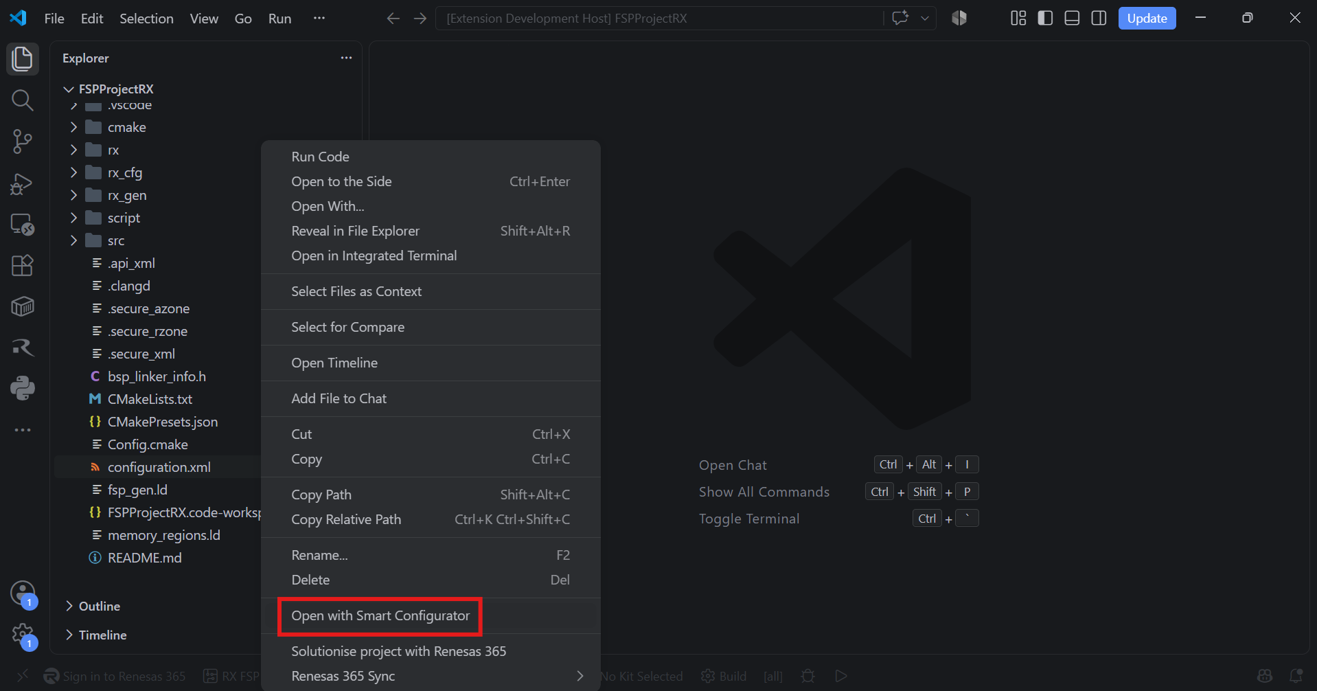
Right click the “configuration.xml” file at the project root, and select the “Open with Smart Configurator” option in the context menu.
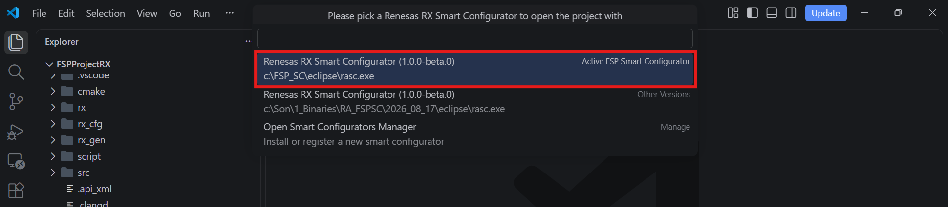
VSCode will show installed [RX FSP Smart Configurator] list, select a [Smart Configurator] from the list to open the project.
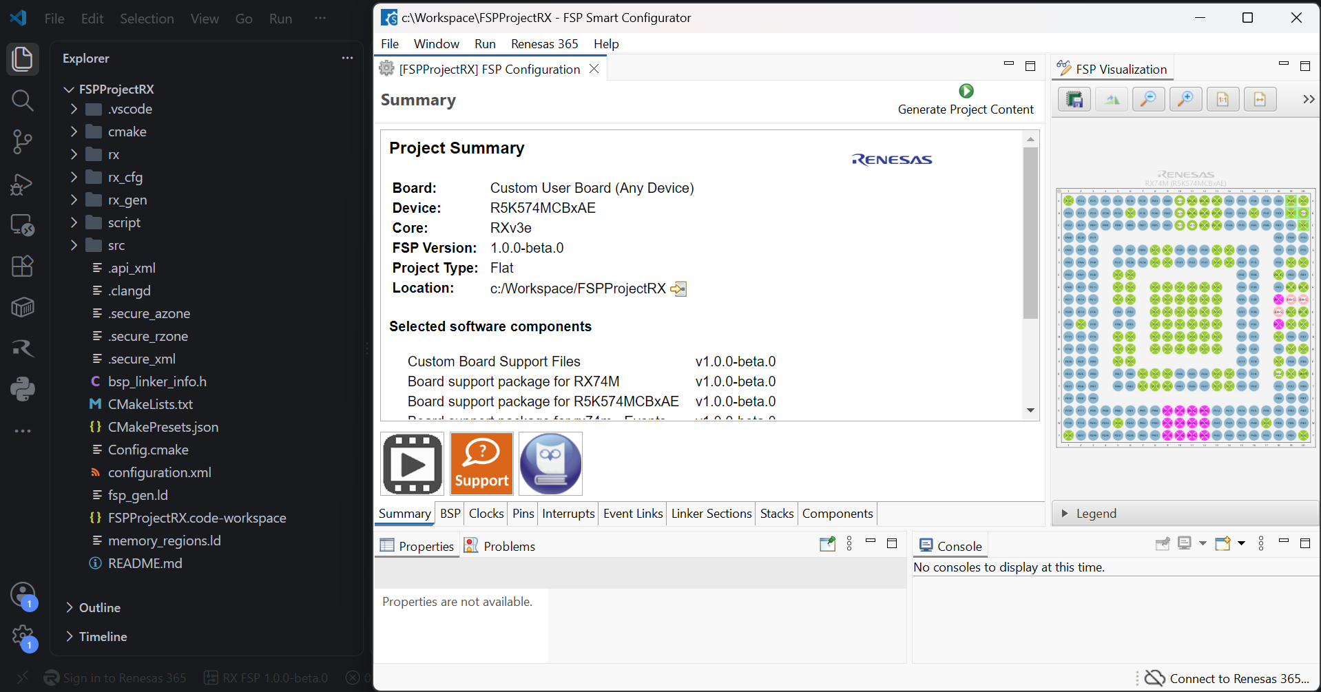
VSCode will open the project in the selected RX FSP Smart Configurator, now you can edit your project configuration in the RX FSP Smart Configurator. Once the changes completed, click the “Generate Project Content” button to re-generate the project content.
20.6. Debugging the Project
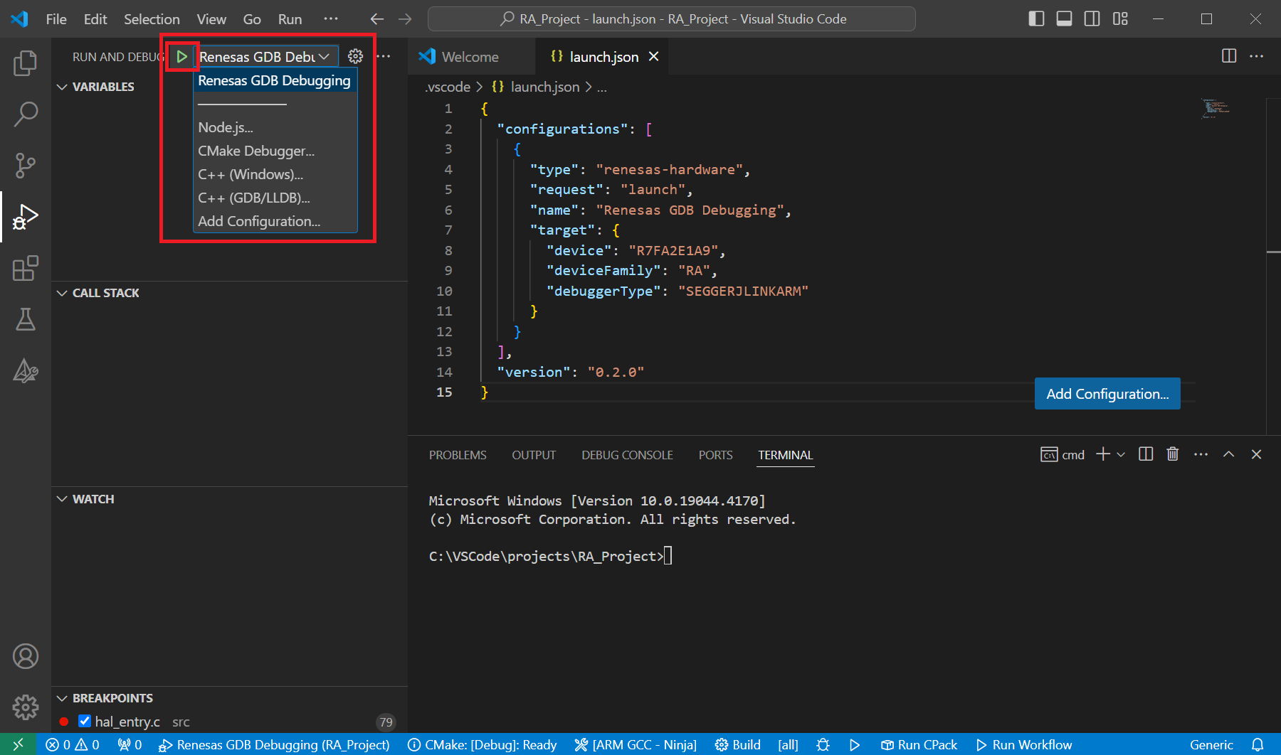
A debug session can be started by selecting the created configuration and clicking the [Start Debugging] button in the [Run and Debug] tab, or pressing [F5] from the keyboard.
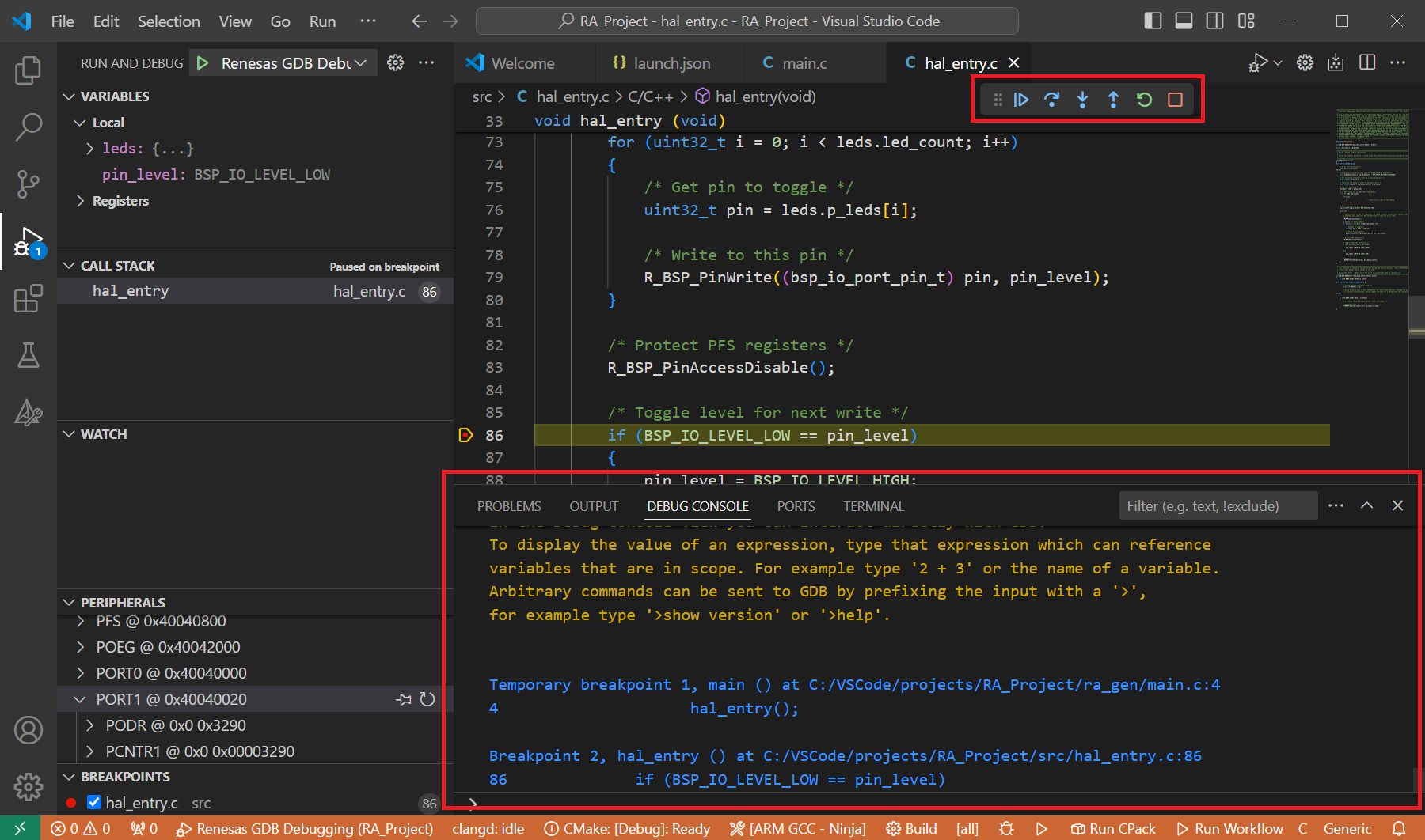
When VS Code starts the debug session, common debug control flow functions like resume, suspend, step into, step over, step out, restart, terminate debug session can be performed via the debug flow control buttons. Also, the [Debug Console] view will contain useful messages during the debug session.
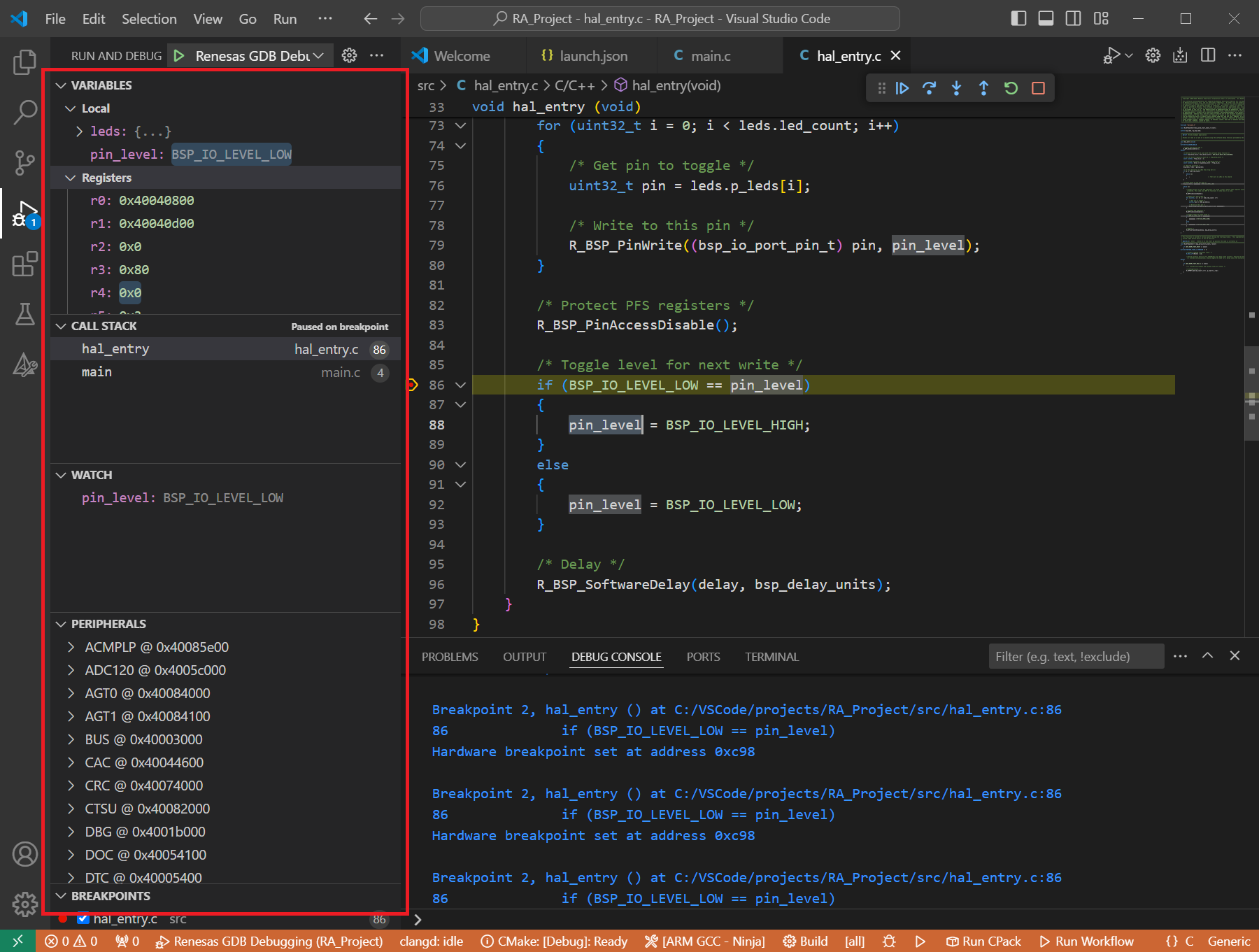
During the debug session, details about the local variables, device registers, call stack, watched variables, states of the peripherals can be accessed at the primary sidebar of VS Code in the [Run and Debug] tab.
20.7. GDB Server launch parameters for RX devices
Reference for common parameters: All common server parameters, including default settings and options applicable to Renesas device families, are documented in the GDB Server Parameters section. The specific parameters of the RX devices are described below.
20.7.1. Connection Settings
20.7.1.1. J-Link
Option |
Details |
|
Description: Specify connection type when using J-Link.
Default Values: None. The J-Link will be selected automatically.
Emulator: SEGGERJLINKRX
Available Values: Using USB: USB=<J-Link Serial number>, Using IP via LAN: IP=<Host Name/IP address: port number>, Using IP via tunnel: IP=tunnel
Example: Select USB with serial number 000051000569:
"serverParameters": { "-uSelect=": "USB=000051000569" }, Select IP with address 127.0.0.1 and port 61234: "serverParameters": { "-uSelect=": "IP=127.0.0.1:61234" }Note: If using IP via tunnel, it’s needed to specify the following parameters.
|
|
Description: Specify the log file for the J-Link to output logging information. If the log file already exists, the contents of the current log file will be overwritten. If the option is empty, no logging information is outputted.
Default Values: None
Emulator: SEGGERJLINKRX
Available Values: Any valid path to log file. The log file path must not contain any blank space characters.
Example:
"serverParameters": { "-uJLinkLog=": "D:/dev_test/e2studio/workspace/project/JLinkLog.log" }Note: J-Link web control panel is prioritized over this configuration. The override option for log file in J-Link web control panel must be disabled before using this parameter.
|
20.7.1.2. Clock
Option |
Details |
|
Description: Specify the Main Clock Source.
Default Values: 0
Emulator: E1, E20, E2, E2LITE, SEGGERJLINKRX
Available Values: 0: EXTAL, 1: HOCO
Example:
"serverParameters": { "-uClockSrcHoco=": 0 } |
|
Description: Specify EXTAL frequency in MHz.
Default Values: None
Emulator: E1, E20, E2, E2LITE, SEGGERJLINKRX
Available Values: Between 0.001 to 99.999
Example:
"serverParameters": { "-uInputClock=": 27.0 } |
|
Description: Specify whether or not to allow manipulation of the main clock source by debugger when internal flash memory is rewritten.
Default Values: 1
Emulator: E1, E20, E2, E2LITE, SEGGERJLINKRX
Available Values: 0: No, 1: Yes
Example:
"serverParameters": { "-uAllowClockSourceInternal=": 1 } |
|
Description: Specify the operating frequency which is used to calculate the performance counter.
Default Values: None
Emulator: E1, E20, E2, E2LITE, SEGGERJLINKRX
Available Values: The frequency in Hz in range 1000 - 999999000
Example:
"serverParameters": { "-uPTimerClock=": 120000000 } |
|
Description: Specify the CPU clock frequency in MHz.
Default Values: Depend on the target device
Emulator: Simulator
Available Values: The frequency in MHz
Example:
"serverParameters": { "-uCpuClkFreq=": 12 } |
|
Description: Specifies the clock division ratio applied to the system clock to generate the peripheral clock.
Default Values: 1
Emulator: Simulator
Available Values: 1, 2, 3, 4, 6, 8, 12, 16, 24, 32, 48, 64
Example:
"serverParameters": { "-uPeripheralClkRatio=": 1 } |
20.7.1.3. Connection with Target Board
Option |
Details |
|
Description: Select the emulator to connect.
Default Values: Auto (Emulator will be selected automatically.)
Emulator: E1, E20, E2, E2Lite
Available Values: Emulator information with format: <emulator type>:<serial number>
Example:
"serverParameters": { "-sn=": "e2:_9es002310c" } |
|
Description: Specifies the connection type to be used when by the emulator when communicating with the CPU on target system.
Default Values: 0
Emulator: E1, E20, E2, E2LITE, SEGGERJLINKRX
Available Values: 0: JTag, 1: Fine
Example:
"serverParameters": { "-uUseFine=": 0 } |
|
Description: Specify JTAG communication speed between the emulator and the CPU on target system.
Default Values: Depend on the debugger type
Emulator: E1, E20, E2, E2LITE, SEGGERJLINKRX
Available Values:
E2Lite: 6.00, 3.00, 1.50
E2: 16.5, 12.5, 6.25, 3.125, 1.562
E1, E20, SEGGERJLINKRX: 16.5, 12.38, 6.188, 3.094, 1.547
Example:
"serverParameters": { "-uJTagClockFreq=": 6.00 } |
|
Description: Specify FINE communication speed between the emulator and the CPU on target system.
Default Values: Depend on the debugger type
Emulator: E1, E20, E2, E2LITE, SEGGERJLINKRX
Available Values:
E2Lite: 1.50, 0.75, 0.50, 0.25
E1, E20, E2, SEGGERJLINKRX: 2.00, 0.75, 0.5, 0.25
Example:
"serverParameters": { "-uFineBaudRate=": 1.50 } |
|
Description: Specify if connecting to an already running target system.
Default Values: 0
Emulator: E1, E20, E2, E2LITE
Available Values: 0: No, 1: Yes
Example:
"serverParameters": { "-uHotPlug=": 1 } |
20.7.1.4. Power
Option |
Details |
|
Description: Select whether to supply power to the target board from emulator.
Default Values: 0
Emulator: E1, E20, E2, E2Lite
Available Values: 0, 1, 2
Example:
"serverParameters": { "-w": 1 }Note: Value
2 is just supported for E2 emulator. |
|
Description: Specify the power voltage supplied to the target board.
Default Values: 0
Emulator: E1, E20, E2, E2Lite
Available Values: 0: 3.3 V, 1: 5.0 V, From 18 to 50: From 1.8 V to 5.0 V
Example:
"serverParameters": { "-z": 0 }: using for 3.3 V, "serverParameters": { "-z": 1 }: using for 5.0 V, "serverParameters": { "-z": 18 }: using for 1.8 VNote: E2Lite emulator is just supported 3.3 V. Just E2 emulator allows to specify a arbitrary value from 1.8 V to 5.0 V
|
20.7.1.5. CPU Operating Mode
Option |
Details |
|
Description: Specify the operation mode set by registers.
Default Values: 0
Emulator: Simulator, E1, E20, E2, E2LITE, SEGGERJLINKRX
Available Values: 0: “Single Chip”, 1: “On-Chip ROM Ext. On”, 2: “On-Chip ROM Ext. Off”
Example:
"serverParameters": { "-uRegisterSetting=": 0 } |
|
Description: Specify the operation mode set by mode pins.
Default Values: 0
Emulator: Simulator, E1, E20, E2, E2LITE, SEGGERJLINKRX
Available Values: 0: Single-chip mode, 1: User boot mode
Example:
"serverParameters": { "-uModePin=": 0 } |
|
Description: Specify if the start up bank needs to be changed, when the target device supports “Dual Mode”.
Default Values: 0
Emulator: E1, E20, E2, E2LITE
Available Values: 0: No, 1: Yes
Example:
"serverParameters": { "-uChangeStartupBank=": 0 } |
|
Description: Specify the start up bank when it needs to be changed.
Default Values: Bank 0
Emulator: E1, E20, E2, E2LITE
Available Values: Bank 0, Bank 1
Example:
"serverParameters": { "-uStartupBank=": "BANK_0" } |
|
Description: Enables or disables cache decoding.
Default Values: 1
Emulator: Simulator
Available Values: 0: No, 1: Yes
Example:
"serverParameters": { "-uCacheDecode=": 1 } |
20.7.1.6. Communications Mode
Option |
Details |
|
Description: Specify the emulation mode.
Default Values: 0
Emulator: E1, E20, E2, E2LITE, SEGGERJLINKRX
Available Values: 0: “Debug Mode”, 1: “Write On Chip Flash Memory”
Example:
"serverParameters": { "-uDebugMode=": 0 } |
|
Description: Specify if the user program should be executed after disconnecting the debugger.
Default Values: 0
Emulator: E1, E20, E2, E2LITE, SEGGERJLINKRX
Available Values: 0: No, 1: Yes
Example:
"serverParameters": { "-uExecuteProgram=": 0 } |
20.7.1.7. Flash
Option |
Details |
|
Description: Enter ID code to unlock the flash memory from the protected state.
Default Values: FFFFFFFFFFFFFFFFFFFFFFFFFFFFFFFF
Emulator: E1, E20, E2, E2LITE, SEGGERJLINKRX
Available Values: 32 hex digit
Example:
"serverParameters": { "-uIdCode=": "FFFFFFFFFFFFFFFFFFFFFFFFFFFFFFFF" } |
20.7.2. Debug Tool Settings
20.7.2.1. General Debug
Option |
Details |
|
Description: Select whether to reset the program after downloaded.
Default Values: 1
Emulator: E1, E20, E2, E2LITE, SEGGERJLINKRX
Available Values: 0: No, 1: Yes
Example:
"serverParameters": { "-uresetOnReload=": 1 } |
20.7.2.2. Memory
Option |
Details |
|
Description: Specify the first address of the working RAM area for debugger firmware.
Default Values: Depends on the target device
Emulator: Simulator, E1, E20, E2, E2LITE, SEGGERJLINKRX
Available Values: Internal RAM area
Example:
"serverParameters": { "-uWorkRamAddress=": "0x1000" } |
|
Description: Select whether to verify data when writing to memory.
Default Values: 0
Emulator: E1, E20, E2, E2LITE, SEGGERJLINKRX
Available Values: 0: No, 1: Yes
Example:
"serverParameters": { "-uverifyOnWritingMemory=": 0 } |
20.7.2.3. System
Option |
Details |
|
Description: Specify whether or not the program being debugged rewrites the internal program ROM.
Default Values: 0
Emulator: E1, E20, E2, E2LITE, SEGGERJLINKRX
Available Values: 0: No, 1: Yes
Example:
"serverParameters": { "-uProgReWriteIRom=": 0 } |
|
Description: Specify whether or not to debug a program that involves rewriting the internal data flash.
Default Values: 0
Emulator: E1, E20, E2, E2LITE, SEGGERJLINKRX
Available Values: 0: No, 1: Yes
Example:
"serverParameters": { "-uProgReWriteDFlash=": 0 } |
20.7.2.4. Start/Stop Function
Option |
Details |
|
Description: Specify if a function should be executed before running user program.
Default Values: 0
Emulator: E1, E20, E2, E2LITE
Available Values: 0: No, 1: Yes
Example:
"serverParameters": { "-uhookEnableStart=": 0 } |
|
Description: Specify the address of the start function.
Default Values: 0
Emulator: E1, E20, E2, E2LITE
Available Values: Any valid hex address.
Example:
"serverParameters": { "-uhookStartFunc=": "&R_BSP_ChangeToUserMode" }Note: This parameter is just sent when allow to execute function before running user program
|
|
Description: Specify if a function should be executed after stopping user program.
Default Values: 0
Emulator: E1, E20, E2, E2LITE
Available Values: 0: No, 1: Yes
Example:
"serverParameters": { "-uhookEnableStop=": 0 } |
|
Description: Specify the address of the stop function.
Default Values: None
Emulator: E1, E20, E2, E2LITE
Available Values: Any valid hex address.
Example:
"serverParameters": { "-uhookStopFunc=": "&R_BSP_InterruptRead" }Note: This parameter is just sent when allow to execute function after stopping user program
|
|
Description: Specify the first address of the working RAM area for start/stop function.
Default Values: 0
Emulator: E1, E20, E2, E2LITE
Available Values: Internal RAM area
Example:
"serverParameters": { "-uhookWorkRamAddr=": "0x20001000" } |
20.7.2.5. Execution Mode
Option |
Details |
|
Description: Enables to stop execution when an INT instruction is executed.
Default Values: 1
Emulator: Simulator
Available Values: 0: No, 1: Yes
Example:
"serverParameters": { "-uEmStopInt=": 1 } |
|
Description: Enables to stop execution when an interrupt is encountered.
Default Values: 1
Emulator: Simulator
Available Values: 0: No, 1: Yes
Example:
"serverParameters": { "-uEmStopInterrupt=": 1 } |
|
Description: Enables to stop execution when a floating-point exception is encountered.
Default Values: 1
Emulator: Simulator
Available Values: 0: No, 1: Yes
Example:
"serverParameters": { "-uEmStopFPexp=": 1 } |
20.7.2.6. RTOS
Option |
Details |
|
Description: When debugging a project with a large number of OS threads the Debug View will always check the status of every thread. Selecting Yes will
force the view to only check the current thread. This speeds up debugger responsiveness.
Default Values: 0
Emulator: Simulator, E2, E2LITE
Available Values: 0: No, 1: Yes
Example:
"serverParameters": { "-uOSRestriction=": 1 }Note:
"-uOSRestriction=": 0: Do not restrict OS thread checking, "-uOSRestriction=": 1: Restrict OS thread checking to the current thread |